7/19/24
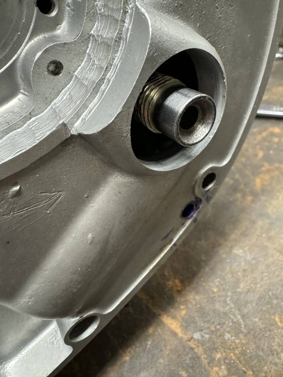
The first part of this post I never imagined I would be writing. We had an unplanned setback that really upset me. Ro-Dy Crankshafts, the maker of our new forged crankshaft made a bonehead mistake that we are now paying for. As I mentioned in previous posts, the new path for the oil flow to the connecting rod bearings is now through the timing side (TS) end of the crankshaft. When converting a stock crank to an end feed crank, a hole is drilled down the length of the TS crank end until it intersects with the stock oil passage. Then a smooth metal extension is threaded or pressed on to the crankshaft and silver soldered to the crankshaft for a rotary oil seal. The hole size that is drilled into the crankshaft is slightly smaller than ¼”, or the approximate size of the oil passages cast into the TS case. I used a 13/64” (.203″) drill to extend the oil path through my TS case.
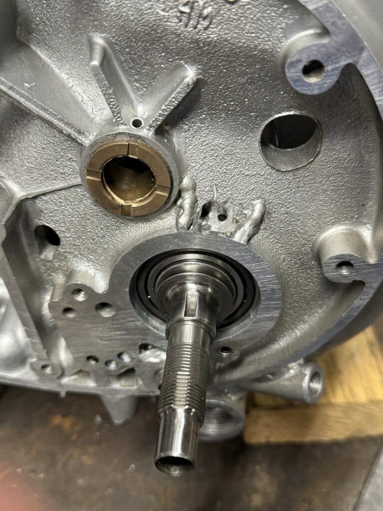
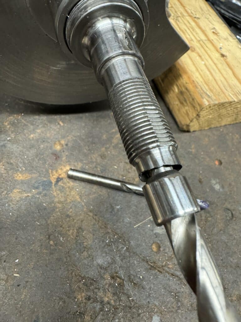
However, something I didn’t catch was that the builder of this crank used a 21/64” drill (.328”), which actually drilled the TS crank end much larger than it needed to be. In theory, this larger diameter shouldn’t matter. In the real world it did. Since the crankshaft has been heat-treated and nitrated, thin parts become very hard and brittle. So brittle that the tip of the TS crankshaft where the oil seal sits, broke off. Because of this oversized bore through the crank end, the wall thickness was about .072” thick where the seal sits, or a little over 1/16”. Had Ro-Dy used the correct drill size, the wall thickness would have been about .135″, over 1/8”, and about double the wall thickness. This would have been robust enough to prevent the brittle end from breaking off. The crankshaft steps up in size a couple of times toward the roller bearing so there is more wall thickness as it does, but the tip was too weak with the oversized hole.
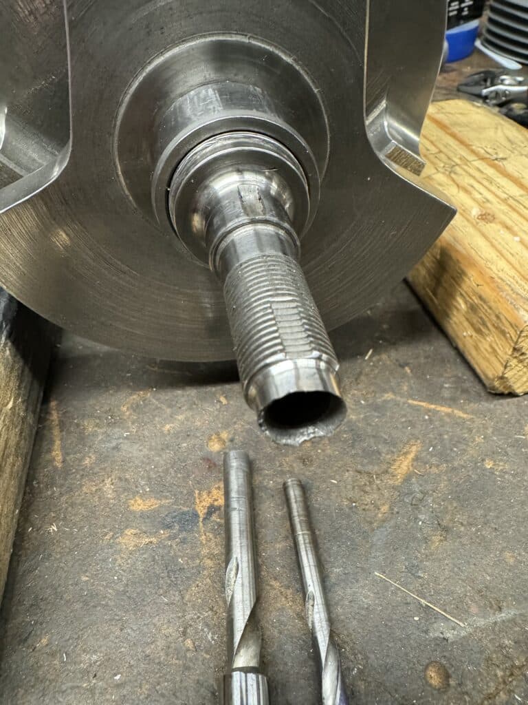
In fact, Ro-Dy crankshafts had sent us 2 crankshafts for me to chose from. They were both built for use with an end feed oiling system. I chose this one since it had a full flywheel while the other crank had a cut-away flywheel. If I was building a drag racing or flat track motor where constant acceleration is needed, the cut-away crank would have accelerated slightly quicker, being about 3lbs. lighter, but this motor is for the street and being able to idle is a consideration. If raced at a venue like the Bonneville Salt Flats, the crank I chose might even have an advantage. Eric has decided to keep the lighter crank to use in one of his bikes at a later date. After the end snapped of my crankshaft, we measured the drilled hole on the second Ro-Dy crank and it was the proper size with a thicker wall thickness.
So now we had a crankshaft that was useless to us without repairs or replacement. Ro-Dy is no longer in business, Greg has retired and sold his equipment and shop. Although he admitted his error in the drill size he chose and said he would take care of it if we sent it back to him, we decided to fix it ourselves for a couple of reasons. The first being a delay of a month or more. Greg would have had to use another shop to repair the crank and we didn’t know how long this would take. Round trip shipping with insurance from San Francisco to Michigan would be a couple of hundred dollars. Lastly, I trust my work more than his at this point. This never should have happened!
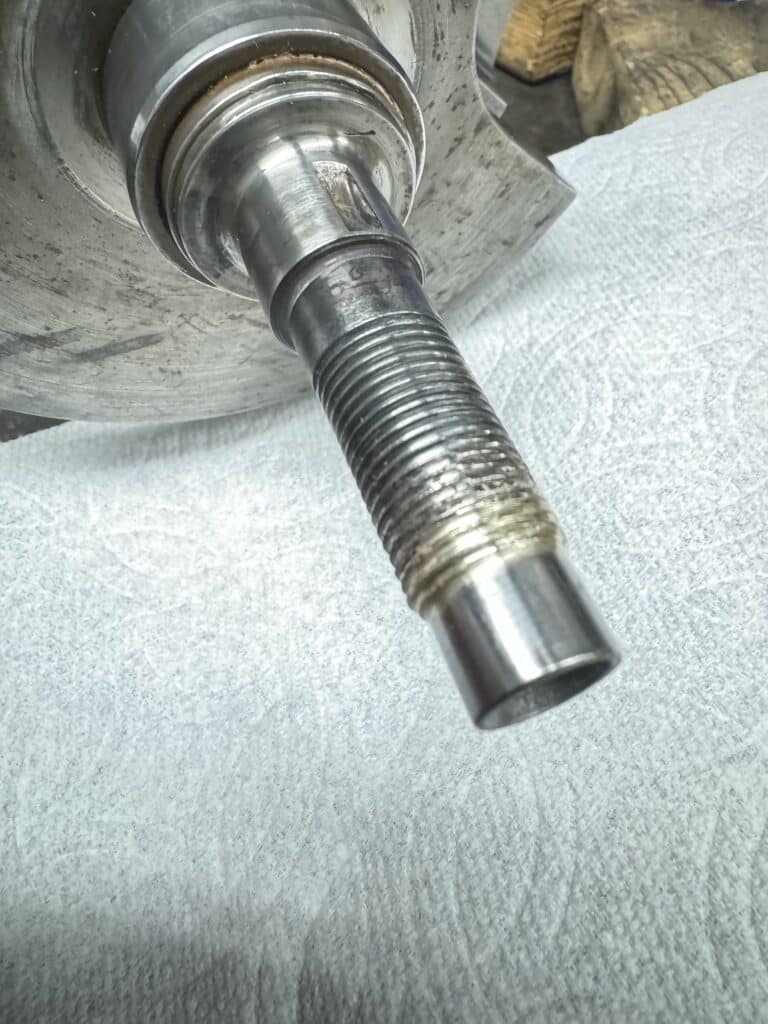
Our fix was to turn a shaft that fit the end of the crank with a 12mm polished end sticking out of the crank for the oil seal to rotate against. I decided to use 4130 steel for this part as it is a tough metal, but hopefully not as brittle as the 4340 crankshaft. Then we would hone the inside of the crank with a 5/16 hone, using acetone as a cleaner. I drilled a 13/64” hole through the middle of the 4130 shaft and turned it down to a sliding fit into the crank with a 12mm protrusion. This shaft is about 1-1/2” long and is to be silver soldered into the crankshaft. Silver solder will do 2 things. First it will seal the crank for the pressure of the oil inside the crank and Second, we hope it will strengthen the crank where it was weakened due to the larger bore. Silver solder has anywhere from 40,00 PSI strength up to about 70,000 PSI, depending on the alloy used. In general, the higher the silver content, the higher the PSI strength. The downside is that higher PSI strength means higher temperature for the solder to flow. The issue at hand is to not overheat the crankshaft and destroy the heat-treating or the nitrating.
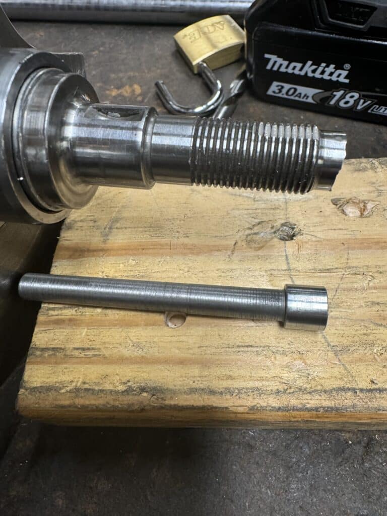
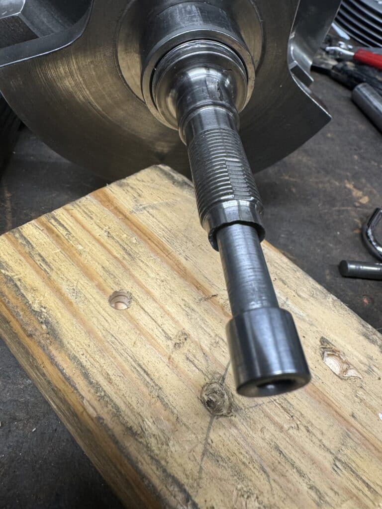
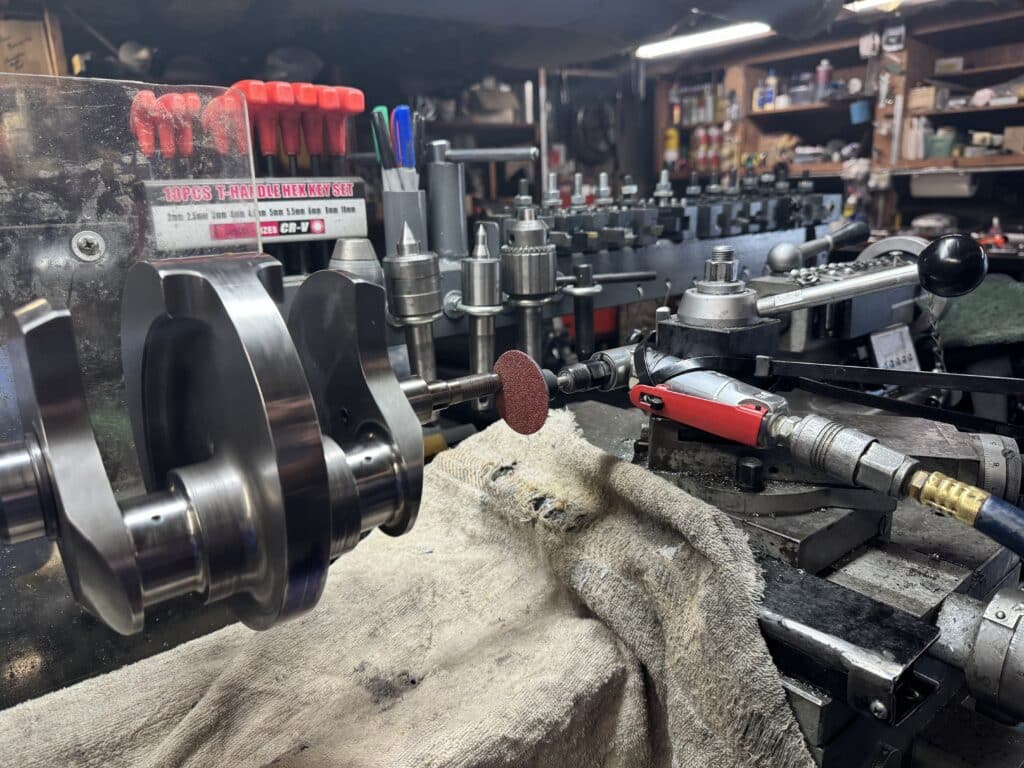
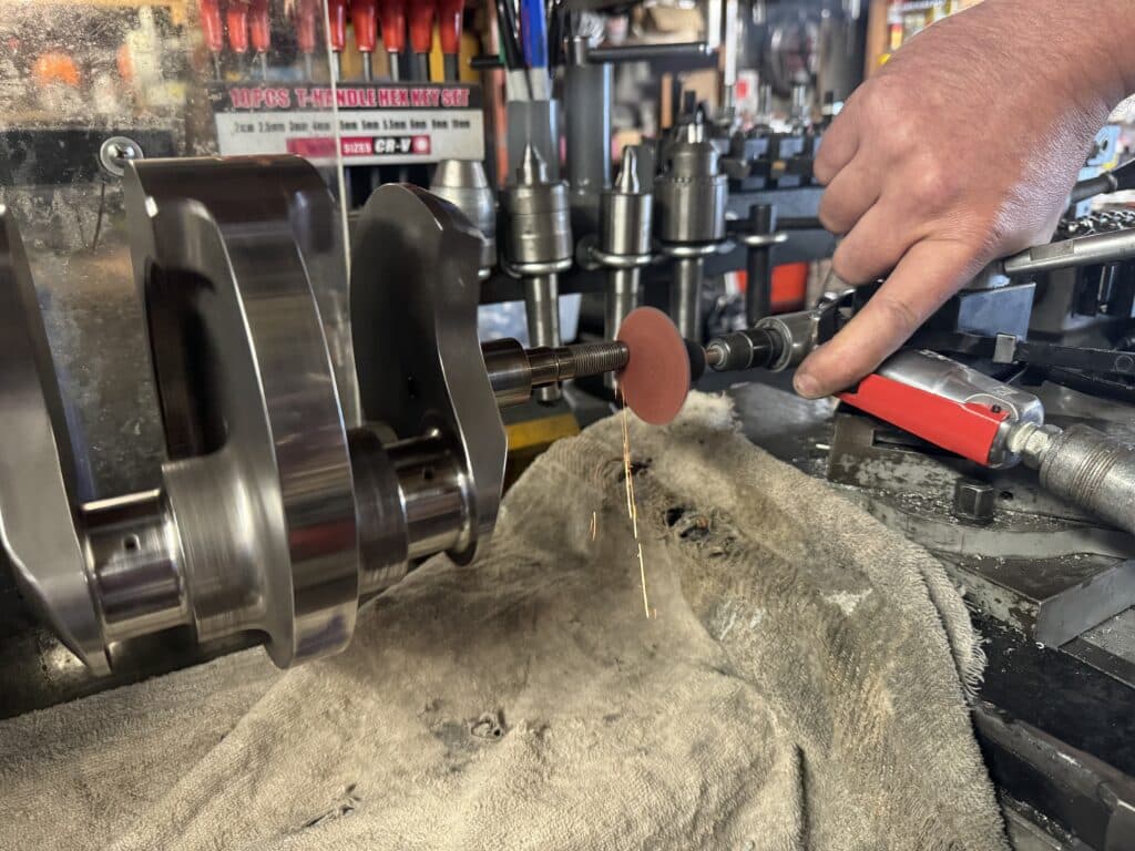
We also had to get the length of the 12mm tip of the crank cut to the correct length for the oil seal cap to function properly. Had the end not broken off, this would have involved a trial fit in the cases with the TS cover in place. The crank protrusion would have been measured and trimmed as necessary. We still had to do this, but now, since the end of the crankshaft is jagged from the break, we had to cut the end of the crank square and to the correct length for our seal and cap. 4340 steel is incredibly tough to turn once hardened and nitrated, and being thin and brittle, it’s even harder to machine. So I rigged an air grinder to the tool post of the lathe with oversized zip ties, to take off not quite 1/4” for the fit we needed. Going slowly, this worked incredibly well.
Leaving the crank in the lathe after grinding, I amply fluxed the new seal shaft as well as the inside of the crankshaft end and slid the parts together. Using a IR thermometer and spinning the crank at a dead slow speed, we heated the crank to about 1,200 degrees, but just over the threaded area. At this temperature the silver solder started to flow into the shaft. We keep the flame only on the threads. Hopefully we got an inch or more of flow into the crankshaft. This is more than enough to seal the end for oil pressure and hopefully we can regain some of the strength lost by oversize drilling. If we affected the heat treating in the threaded area, it shouldn’t matter too much as these LH threads are for a nut to hold the timing gear and oil pump pinion gear in place, and heat treating isn’t really needed in this area.
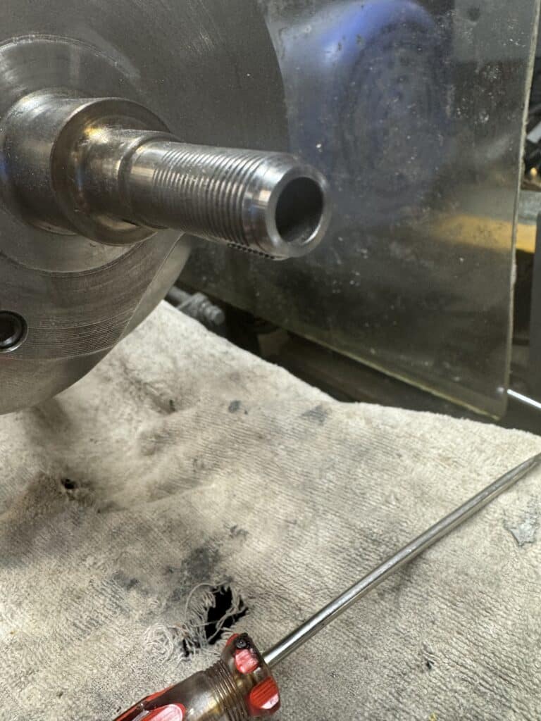
After polishing the end of the TS end of the crank to remove the bluing caused by the heat of silver soldering, we are back in business.
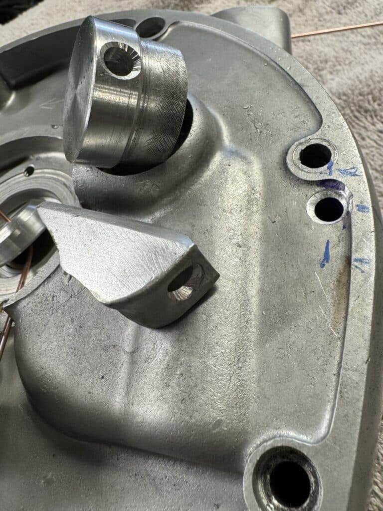
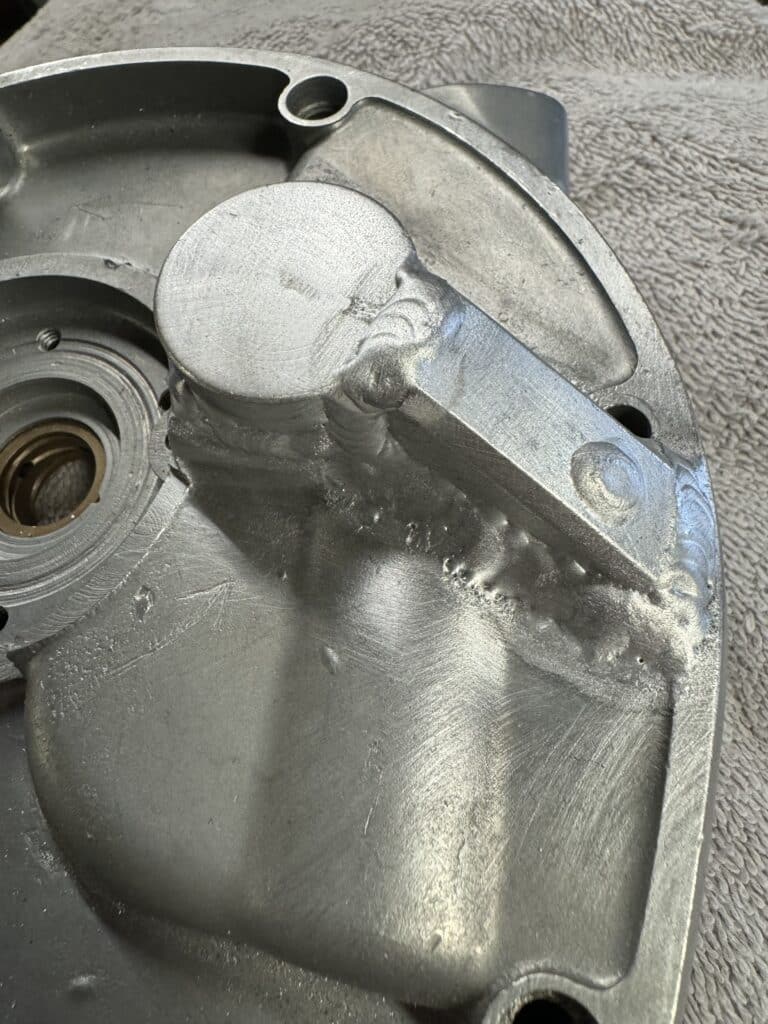
In order to complete the case modification for the new path of the oil into the end of the crankshaft, I made a connector piece from a block of 5/8” wide aluminum, drilled and flared the holes for good alignment for the oil flow, and took it to Shawn Campbell https://www.instagram.com/narleyfab/ for welding. Shawn welded this block along with the seal cap, onto the TS cover case. Once the seal and the O-ring are in place and the cases bolted up, the roller bearing conversion and new path of oil flow should be complete.
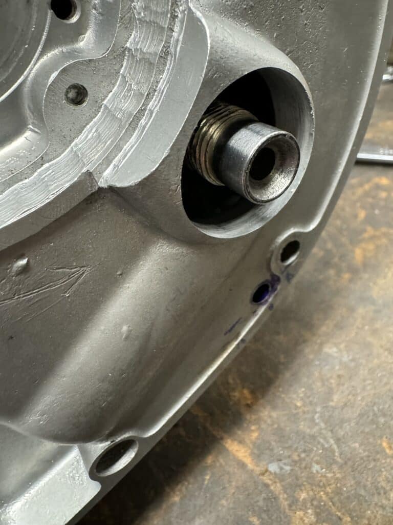
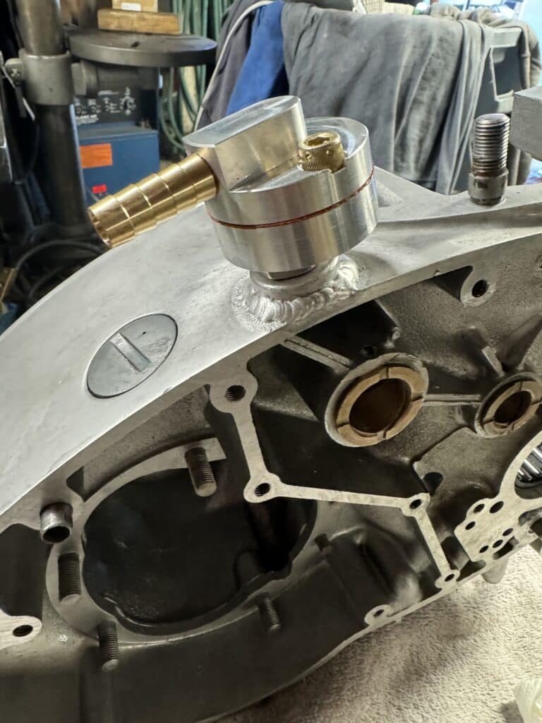
The next modification to the cases is the placing a reed valve breather in the case to relieve the pressure built up in the engine while running. We got the part from Jim Schmidt https://jsmotorsport.com and he modifies a BMW breather for this purpose for his Norton’s. Shawn Campbell welded a block I made where I wanted the breather to be placed, so that there would be a little more thickness where I drilled and tapped into the case. We are blocking off the stock timed breather that the BSA factory used as this new breather is much more efficient. The exit hose from the breather is larger than the stock breather hose, so the return to the oil tank will have to be enlarged to accommodate this larger diameter hose, as well as welding another fitting to the top of the oil tank to relieve pressure in the tank from the breather. This hose will exit at the rear of the fender.
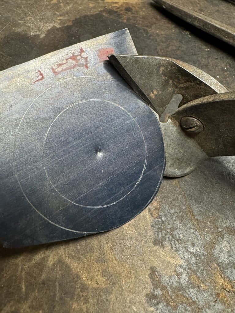
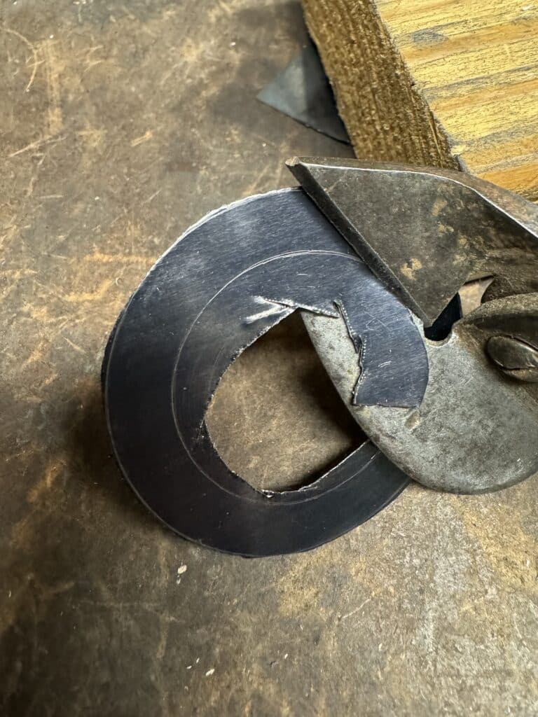
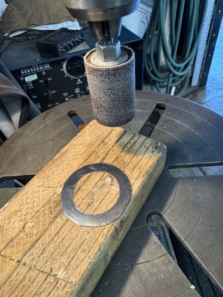
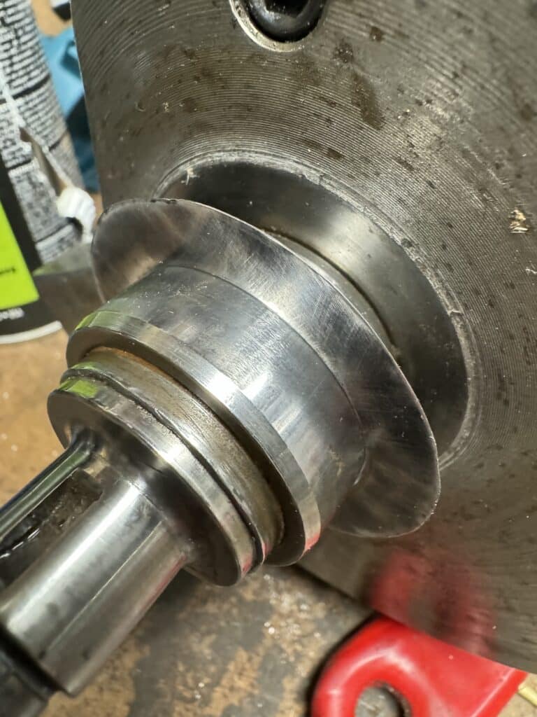
Now that we have roller bearings on both sides of the crankshaft, a thrust washer was needed. So we bolted the case halves together and tightened them with the crank installed to measure this thrust clearance. We were able to place a dial indicator on the end of the crankshaft to measure the side to side clearance between the crankshaft and the cases. We wanted .003” on a cold motor and the clearance was .013”. This meant we needed a .010” spacer to act as a thrust washer. It needed to have an ID of 37mm and an OD of about 54 mm. After spending way too much time online trying to find one, I ordered some shim stock from Amazon and cut and ground my own shim. We now should have the .003” end clearance we need.

Comments