9/9/24
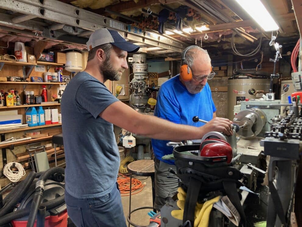
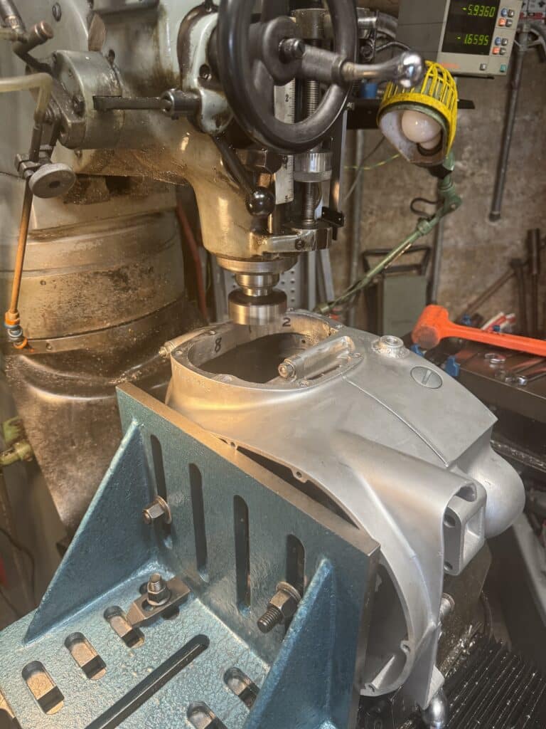
One of the last machining jobs to the engine cases is called decking. For us, it involved using a large 90 degree angle plate bolted to the mill table, and fly cutting the top of the cases to insure that the cylinder barrels sit exactly parallel to the crankshaft. Since the case sides were already machined flat at their sides and exactly 90 degrees to the crankshaft, the case top needed to be milled flat and parallel to the crankshaft also. We used an 8” cast iron angle plate for this milling operation. Using a square, I placed the angle plate on the mill table and bolted it down. With a dial indicator, we checked the angle plate for exact 90-degree up and down trueness to the mill table. Luckily, our angle plate is dead on but if not, we would have had to use trial and error fitting with shims to achieve this 90 degree trueness.
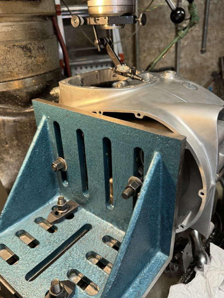
The cases were bolted together and torqued tight, and the cylinder studs removed. Then the drive side was bolted to the angle plate. This decking procedure can only be accomplished from the side-to-side axis. (parallel to the crankshaft). For front to back axis, we used a dial indicator and tapped the cases with a dead blow hammer, until we had the same reading on the front of the case as on the rear. This insured the barrels would not tip forward or to the rear. Once satisfied, we snugged everything tight and made our cuts. These cuts potentially raise the compression of the engine, so we took as little as possible in small light cuts until we made 100% contact across the top of the cases. In total, it took about .014” to get us flat and parallel.
However, things are quickly coming to a standstill on our BSA Spitfire Hornet project. We are scrounging around for things to do on the motor because the new 80mm big bore aluminum cylinder barrels, due to arrive last March, are still not here. When they did arrive a couple of weeks ago to the US distributor, apparently the Nikasil coating to the cylinder walls arrived flawed from England, where alloy barrels are cast and machined. The US supplier supposedly sent them out for a re-do of this coating and we have no idea what this time frame means. Not having the barrels stops us in our tracks. I don’t know if more machining to the cases is necessary once we finally receive them, to allow the barrels to fit into the cases. I can’t purchase the connecting rods until I have the barrels in order to be positive of their length, I need the barrels to check that piston clearances are correct, and only then can I send the rotating and reciprocating parts out to be balanced.
Supposedly they will be ready in “another few weeks”, but I have heard this same story for months. If our project was for a Triumph there would be several choices, but for a BSA, this seems to be the only game in town, short of casting and machining our own set of barrels.
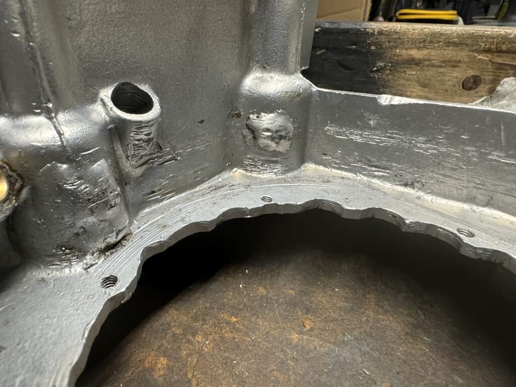
To keep going on the project we are doing pick-up work. One small project was to build an internal chain guard out of 1” x 1/8” mild steel to protect the softer aluminum case from a very lose, or worse, a broken chain in the area where the chain wraps around the transmission drive sprocket. The photos show scaring from previous chain issues, and hopefully this guard will lower the chances of catastrophic engine case breakage from a chain failure.
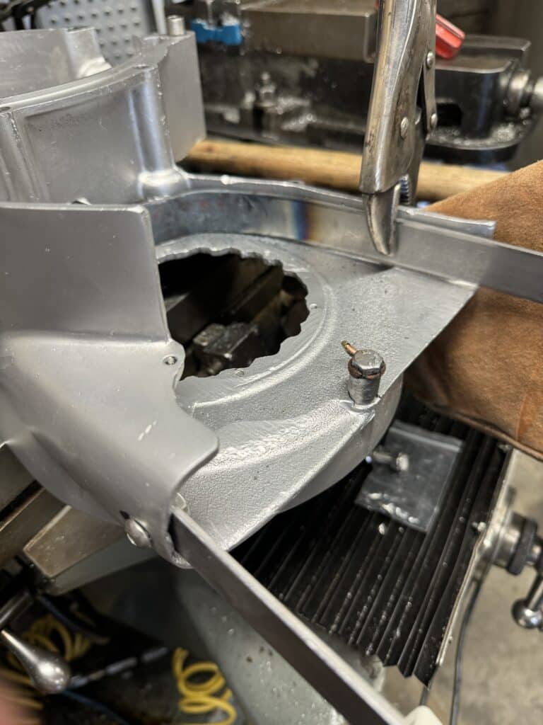
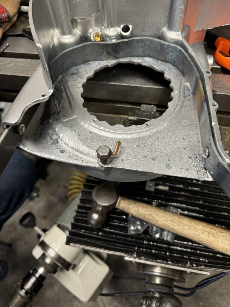
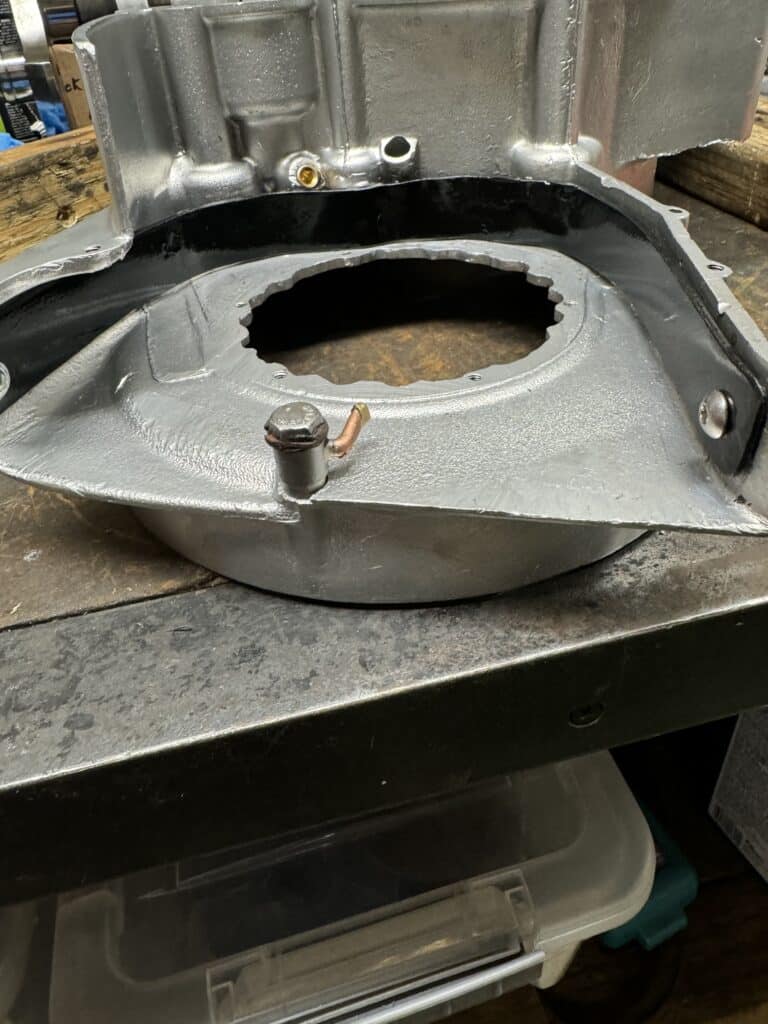
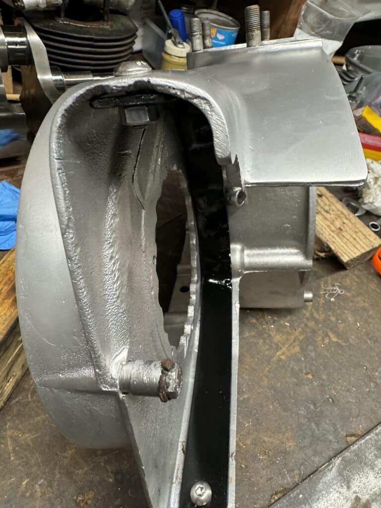
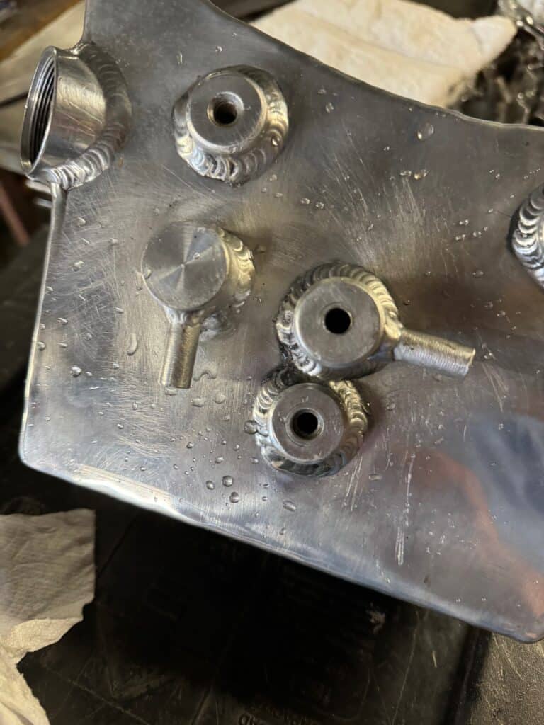
I also modified my existing aluminum oil tank in order that the oil tank would have the same size fitting size as the new reed valve breather. The fitting on the tank was smaller than the vent outlet from the engine breather and now this is corrected. I also machined a second oil tank breather, which was welded onto the top of the tank, in order to relieve any pressure inside the oil tank. The stock timed breather has been plugged with a brass 1/8” pipe plug (see photo with the new chain guard). The old breather dripped onto the chain and the ground, creating a gooey mess. British bikes weren’t often called “road oilers” without good reason.
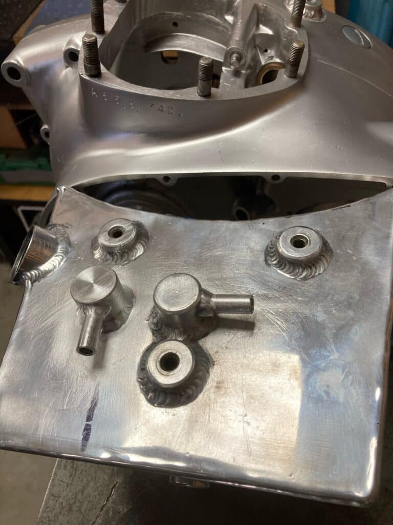
One last modification to the oil tank came about when I was cleaning out the chips from drilling the second breather outlet. After using acetone, air, and finally soap and water to be sure everything was clean and chip particle free, I put the oil cap on and flushed water from a garden hose back into the tank. When it filled, water shot out the new ¼” exit vent, but only dribbled out the original vent pipe that I had welded on a new ¼” outlet pipe. As it turns out, this tank was designed with a vent just to relieve any pressure that might be built up from the return oil line into the tank. Therefore, the pressure relief hole under the relief cap was only 1/8’ or less.
To remedy this, I drilled down through the center of the cap with a ¼” drill, into the 1/8” hole and through into the oil tank. Once this hole is welded up on top of the oil cap, a ¼” flow will exit the reed valve engine breather, enter the oil tank with a ¼” pipe carrying engine pressure and some oil, and exit the oil tank with (hopefully) just air through a ¼” hose to the rear of the bike. That’s the theory and a small filter or catch container can be added if I’m wrong.
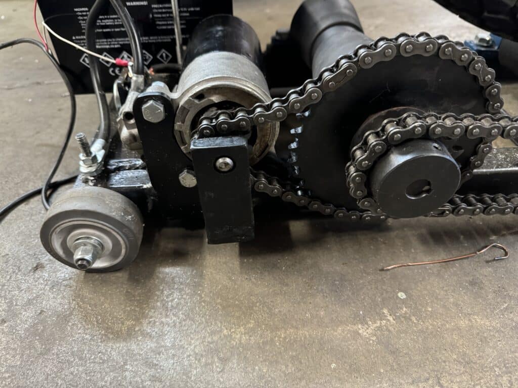
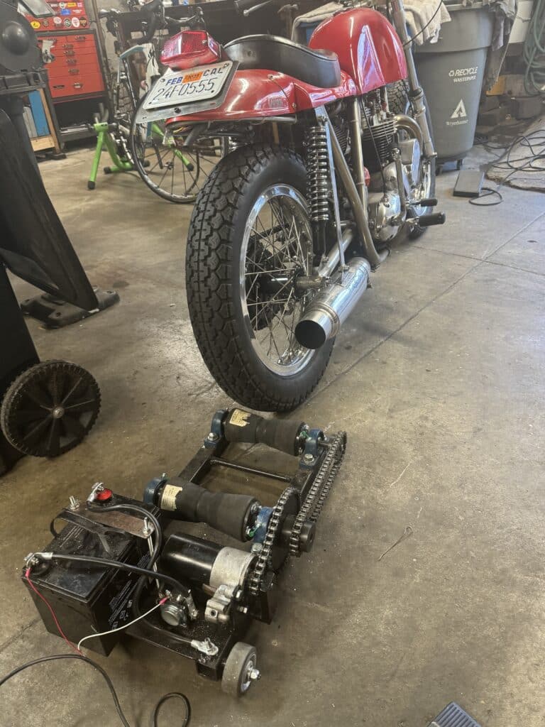
We also went back to work on the paddock starter. I bought a 9-tooth sprocket for the starter motor to replace the 16-tooth sprocket, which is welded to the starter motor now. Unfortunately, after a days work of tearing apart and machining the old hardened sprocket off the starter shaft, welding the new 9-tooth sprocket onto the shaft and re-assemblying the starter, it still did not have quite enough speed (power) to get the Rickman started. A 9 to 36 tooth sprocket setup just won’t turn the motor fast enough in any gear we tried. The next plan is to get a much larger sprocket, maybe a 72 toothed one, or possibly a gear reduction starter motor is another option. A gear reduction starter motor could avoid moving everything now welded and bolted in place. I’m trying to research this a little as the rollers will have to be moved and the rear one raised to accommodate this almost 12” in diameter sprocket! At least I haven’t made a chain guard yet! Bummer.
We are also starting on the cylinder head work and modifications. We are using bronze Kibblewhite Precision Machining Triumph 6mm guides. These are available in .003 oversize which is perfect to press into my cylinder head. I plan to use either 6mm or 7mm valve stems with the oversized valves, so the guides will need to be reamed and honed to size. An advantage to these guides is that they are already machined for Kibblewhite valve oil seals. Eric has been using CAD and 3-D printing to make stainless steel inserts that raise “the floor” on the ports for a better venturi air flow on his Norton, and I’m sure we will be experimenting with this on the BSA also. Check out his articles in this blog about his work. We will start the porting to the head soon.
Also on our “out of sequence” but still needed to get accomplished for our project is repairing the blistered cancerous flaws to one side of the original fiberglass fuel tank. This came about from unknowingly leaving unleaded fuel in the tank, sitting on a shelf for a couple of decades. Out of sight, out of mind. The plan is to repair the damage with fiberglass, prepare for paint, and then coat the inside of the tank with Caswell 2-part epoxy gas tank sealer. Then I’ll paint the tank, clear coat the outside it with fuel resistant sealer and we should be good to go. I coated both plastic tanks for my Rickman Triumph a couple of years ago with Caswell sealer and have had zero issues with unleaded fuel since (except we still drain the carburetor fuel bowl when finished running the Rickman!)

Comments