10/31/24
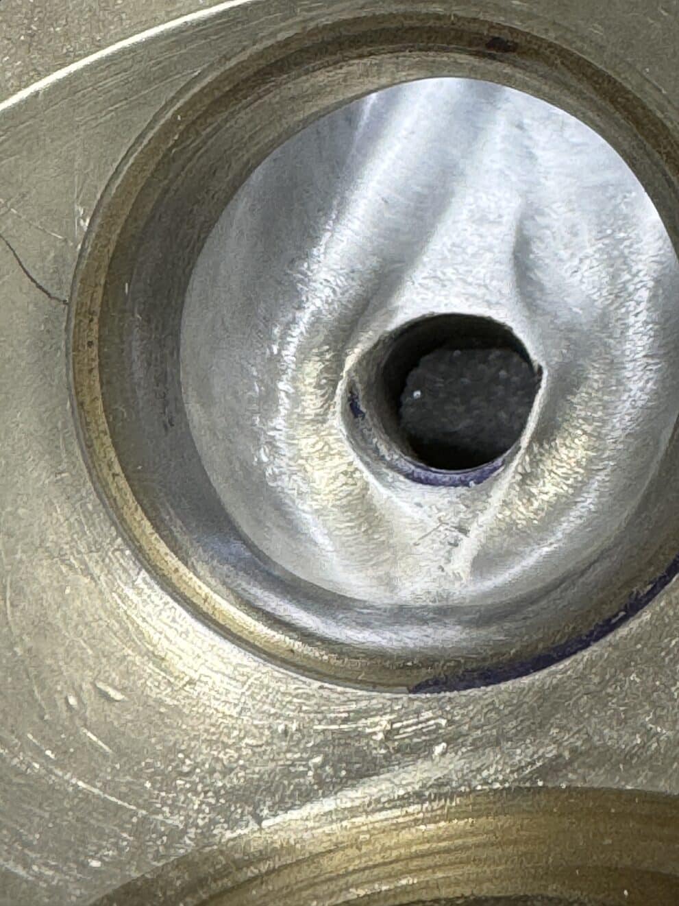
We still have no word about the arrival of the cylinder barrels except “soon”, so we started in on porting the head. My guess is porting will gain upwards of 20% more power than a stock head. Performance is dependent on how much and how quickly fuel/air can enter and exit the motor. Porting is one of the best ways to maximize the power from a high lift, long duration camshaft like we are using. We are using a model of Harley’s XR750’s port shape for our guide, as these heads have years of research and racing development in their flow design. The Harley factory raced the XR 750, and their head was actually cast with proven flow characteristics. We also have been following the photos and reports online from Mark Parker in Australia, who has done amazing head work on A65 BSA heads.
There are several major issues to head modification we are attempting to keep in mind. The first is enlarging the port for increased flow. Our head had minor porting done to it 50 years ago when I installed 34mm Mikuni carbs, but that was just a shallow taper into the head where the new larger manifold attached. The intake bore of the 1964 head was a 27mm round bore. Eric has an A70 BSA with the latest head, which has a 29 mm round bore. We don’t know what year BSA changed the intake port size, but a guess would be 1966, as that was when the BSA Spitfire Mark 3, supposably BSA’s fastest bike until the A70 was introduced. But this is just a guess. Our goal is to enlarge the port as close to 34mm wide as possible in an ovalized shape. We are close to that now at 33.5mm, but we need to have new intake manifolds bolted on to see which side needs more grinding to align with the manifolds. New manifolds are needed for the larger 36mm Mikuni carbs we will use. The manifolds will be 3D printed in aluminum and go from 36mm round at the carb and taper to 34mm wide oval to match the port shape.
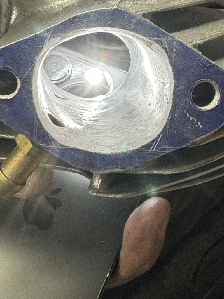
Before and After
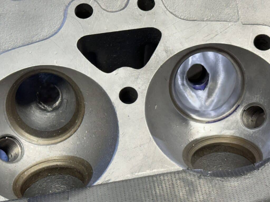
Besides enlarging the ports for volume of flow, most tuners feel what is even more important is the velocity of the flow. Because of the shape of the combustion chamber and the airflow around the valve and valve stem, we are attempting to create a Venturi effect to speed up the air/fuel mixture into the cylinder for combustion. A way to do this on a nominally aspired motor (not turbo or supercharged) is to raise the floor of the intake port and then taper it down further into the port. There are several methods to do this including building up and shaping the floor with JB Weld. Eric is using a CAD drawing program to draw the shape of the design of an insert, then uploading the design for bidding by various 3D printing companies around the world. This design was then 3D printed in aluminum (see photos below). Using the XR 750 model, the ratio of port width to port height can be obtained with these inserts. The inserts will “squeeze” (a Venturi effect) the flow, causing the incoming air/fuel mixture to speed up after passing by them and on into the cylinder. The height the XR 750 uses is about 26.5mm to 27mm from floor to the roof of the port so we are shooting for this. There is a flange cast into the design that will hold the floor inserts in place. Eric has written about this in this blog so check it out for more information.
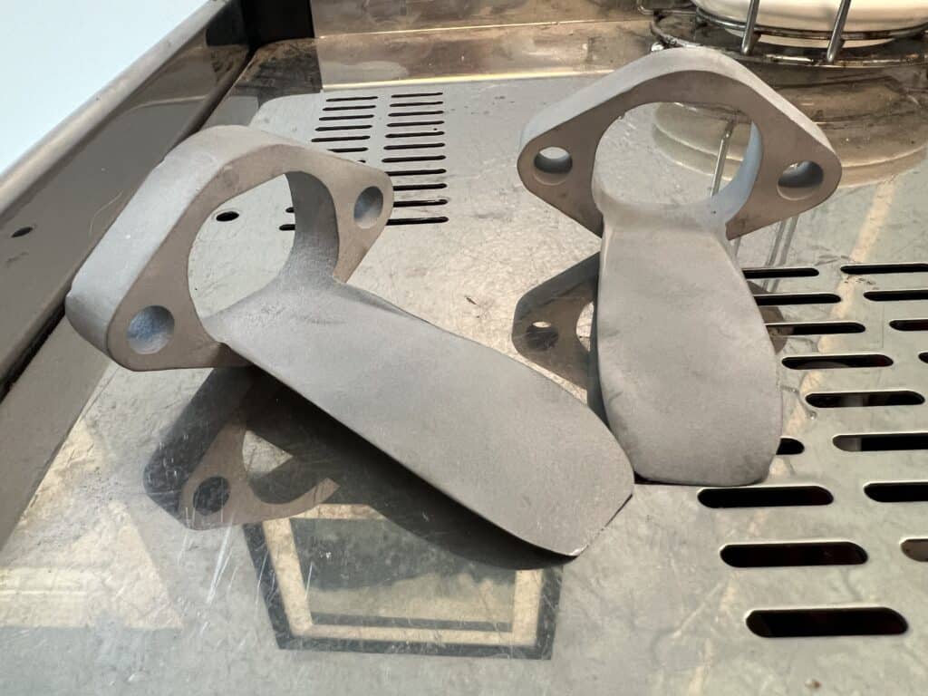
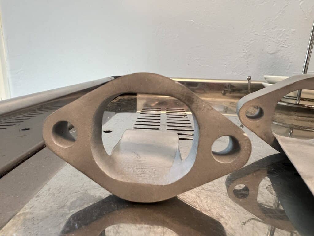
For the exhaust ports an insert was made, but in the opposite shape. This insert will be held against the floor of the exhaust port but raised up as it goes into the exhaust pipe. This is to stop as much “reversion” as possible. The cams on performance engines have overlap, which is when both valves are open at the same time at the end of the exhaust stroke and the beginning of the intake compression stroke. The more lift and duration the cam has, the more likely for reversion to take place. The piston actually pulls back in some of the exhaust gases along with incoming gases, causing a slowdown of exhaust flow. Flow testing of ports with colored dyes has shown that the exhaust flow is mostly toward the roof of the port, so placing this dam at the floor does almost nothing to impede flow and actually increases it. Eric designed and 3D printed these inserts out of stainless steel rather than aluminum because of the heat of combustion on the exhaust side. A ring is cast into the insert that will position the insert and allow it to be held in place by the exhaust pipe.
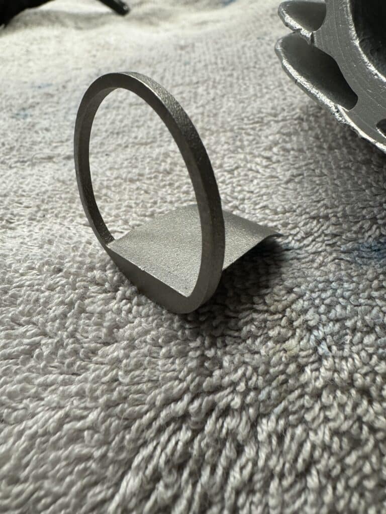
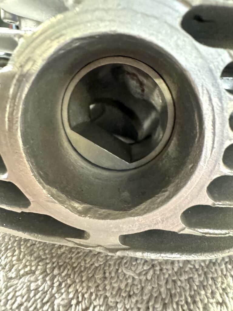
Thankfully, compared to the intake ports, very little material needs to be removed from the exhaust ports. For us, porting the intake side was very slow and somewhat nerve-racking. We were constantly trying to create a shape with a die grinder and long burrs, without going too deep and grinding a hole outside the port. For the most part we were successful but did go through in one spot on the first intake port we attempted. Using the knowledge gained from the first port, we were successful with the other intake port. The small break through we created was welded up by Shawn Campbell. Unfortunately, 2 fins needed to be removed for the repair and then replaced, but Shawn is fantastic at fin repair as can be seen in an earlier post, and below. All in all, we feel we were able to obtain the maximum size and shape possible on this head and the power increase should be large.
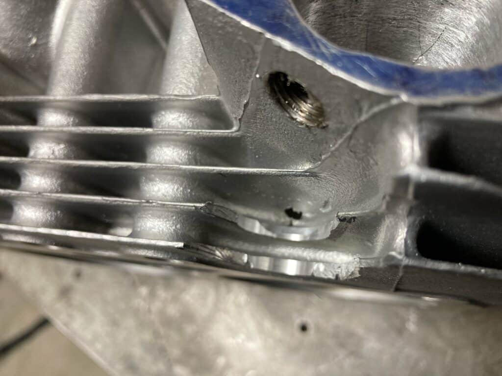
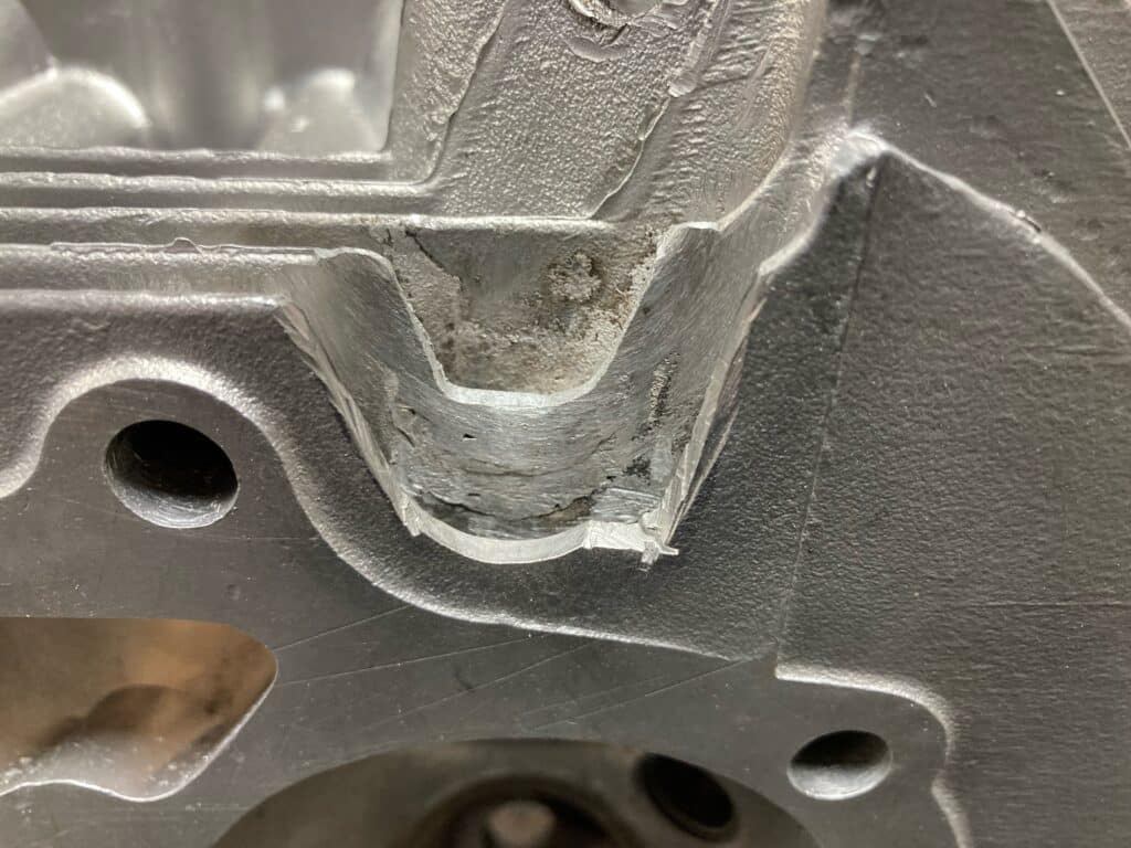
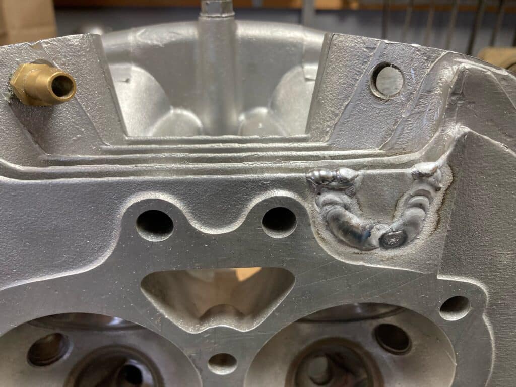
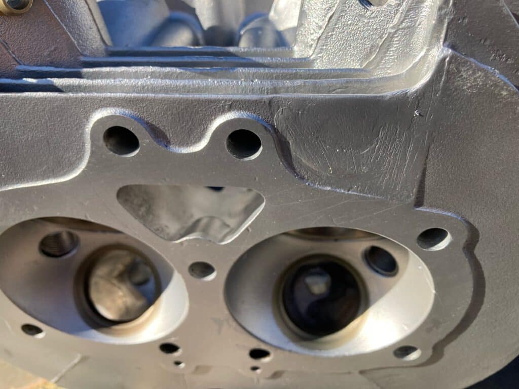
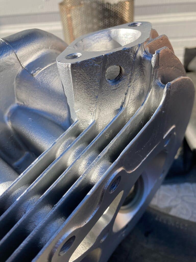
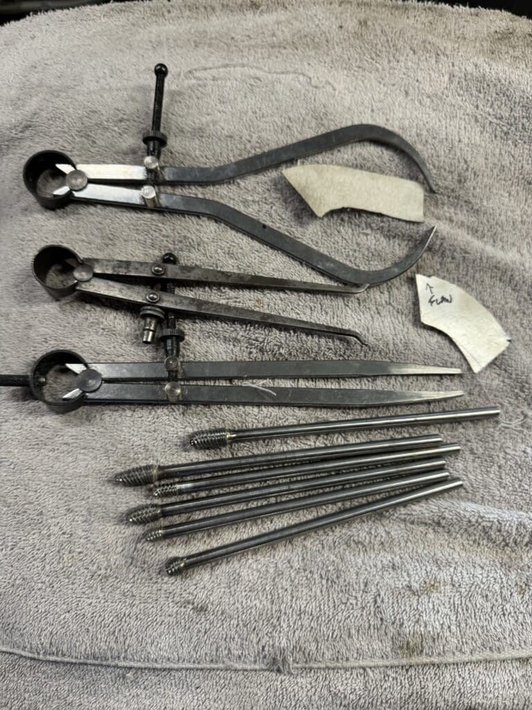
Although we are taking measurements with calipers every ½” or so down each port to try and match the flow to each cylinder, a more precise method would be a vacuum flow bench to measure the precise volume of air traveling through each port. Eric wanted to 3D print a cup that could place a vacuum hose over each cylinder and using water in a tube, measure the height of the water for each cylinder created by the vacuum. Then we could adjust the porting to the lesser flowing port, attempting to equalize them. But when Eric brought the head to Shawn for welding repair to the port, Shawn showed Eric a partially finished flow bench he was working on. Eric said he could design the parts needed to finish it in CAD and have them 3D printed. Eric has the flow bench now and he will get it working soon. We will be able to see the difference between both ports on this head, and also differences between the air flow of other heads, both stock and modified.
Our next task on the head is to insert new bronze Kibblewhite Triumph valve guides, cut out the valve seats and install new ones for the larger 44.5mm intake valves we are going to use. The exhaust seats will be replaced and used with stock sized valves. Intake and exhaust valves will both have 7mm stems and made from stainless steel. This project should appear in our next post.
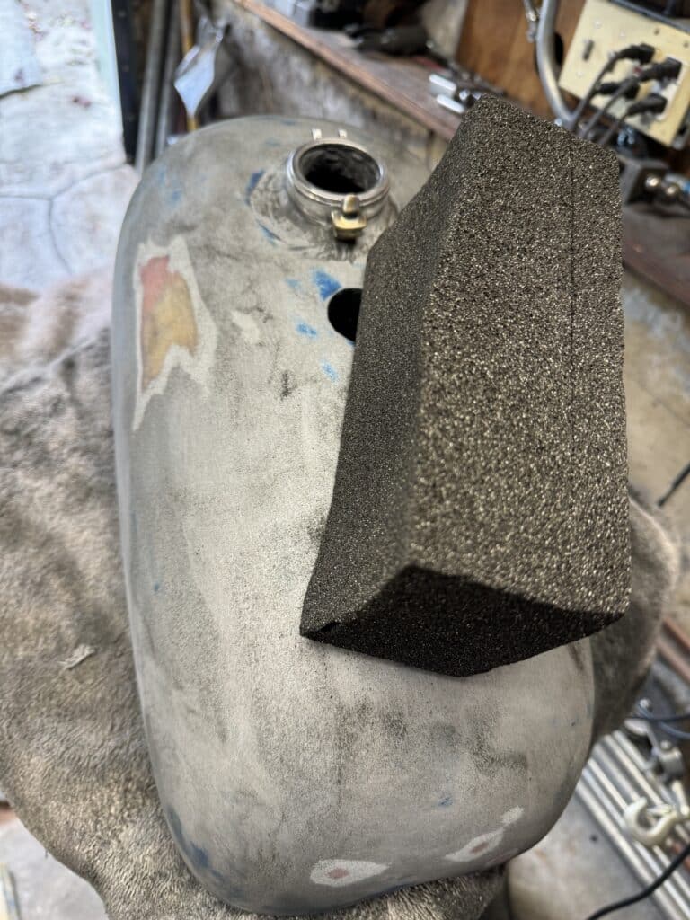
The other project we are working on is repair, sealing, and painting the gas tank. I cut out the blisters mentioned in our last post with a razor knife, removing all the soft material. Using several layers of fiberglass cloth and coats of resin, I achieved a solid repair. Sanding between coats with a dual action (DA) sander gave me a flat, strong repair. Next, using the DA sander and then a brick of pumice, I went over the entire tank to assure a flat, ripple free finish while also removing old paint. Pumice blocks for flat and curved surfaces work extremely well, a method I learned when I was 17 and built a ski boat that I fiber glassed. Pumice can be sourced at restaurant supply stores, marine stores, and of course Amazon. Sanding with a rubber block using finer and finer sandpaper removed the scratches from the pumice and rougher sandpaper.
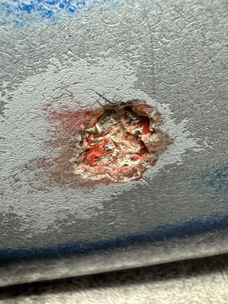
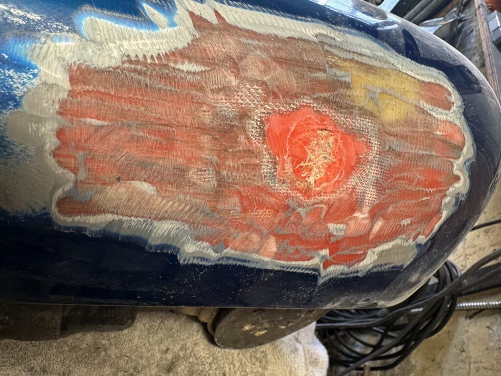
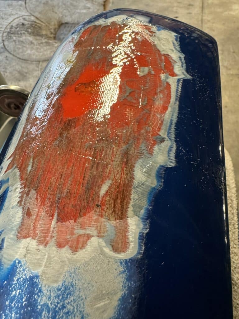
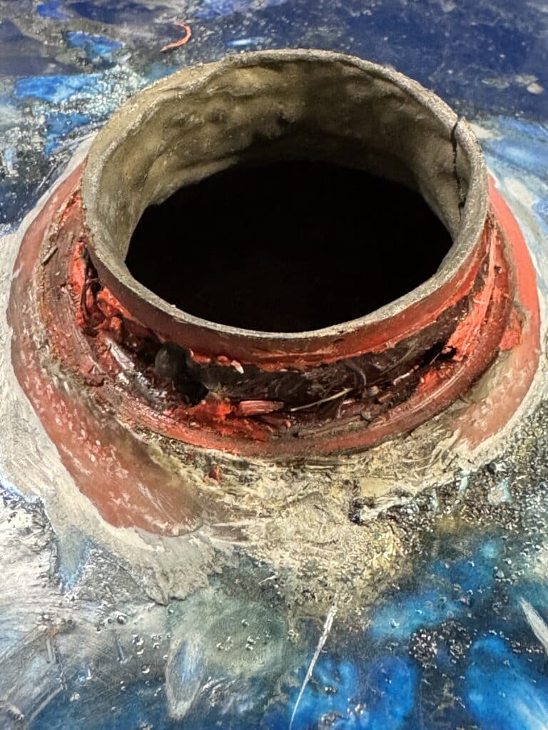
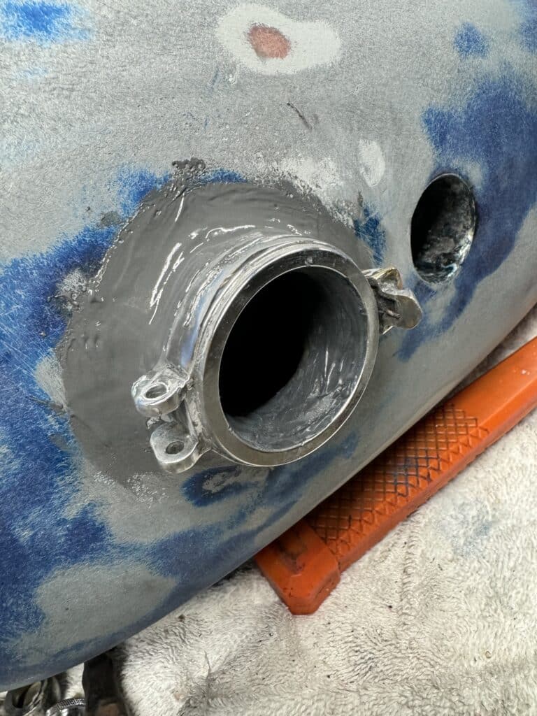
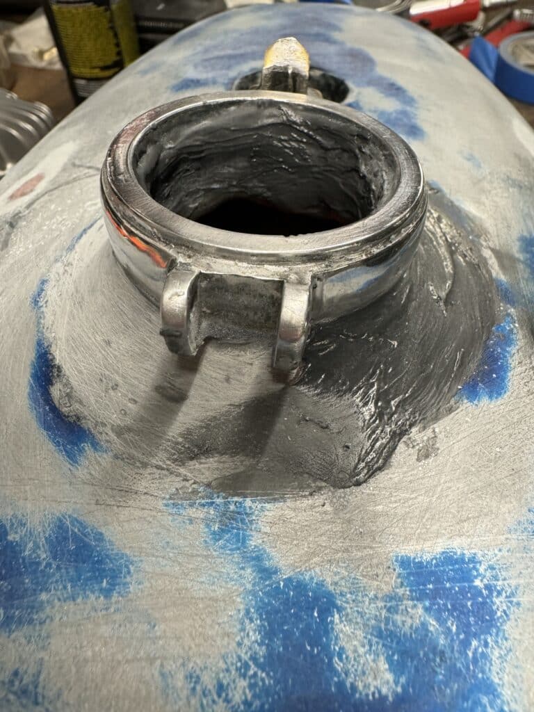
The Monza style filler cap was also not secured to the tank well and had always leaked. Using a heat gun, we wiggled it free from the tank, cleaned up the area, and reset it in a thick bed of JB Weld. It’s now solid and hopefully leak free.
But first, I wanted to seal the inside of the tank with Caswell, 2-part epoxy sealer and before that process could begin, the inside of the tank needed to roughed up and cleaned with sharp drywall screws shaken around in a bath of acetone. The inside of the 2.1-gallon tank is coated with 40-year-old smelly dried gas now in a varnish form. It took almost a gallon of acetone with repeated rinses to finally remove the varnish, leaving a clean, roughed up surface for the sealer to adhere to. After this process, another 3 or 4 rinses with hot water and Dawn soap along with drywall screws, then just repeated rinses with hot water, finished the interior of the tank cleaning and rinsing.
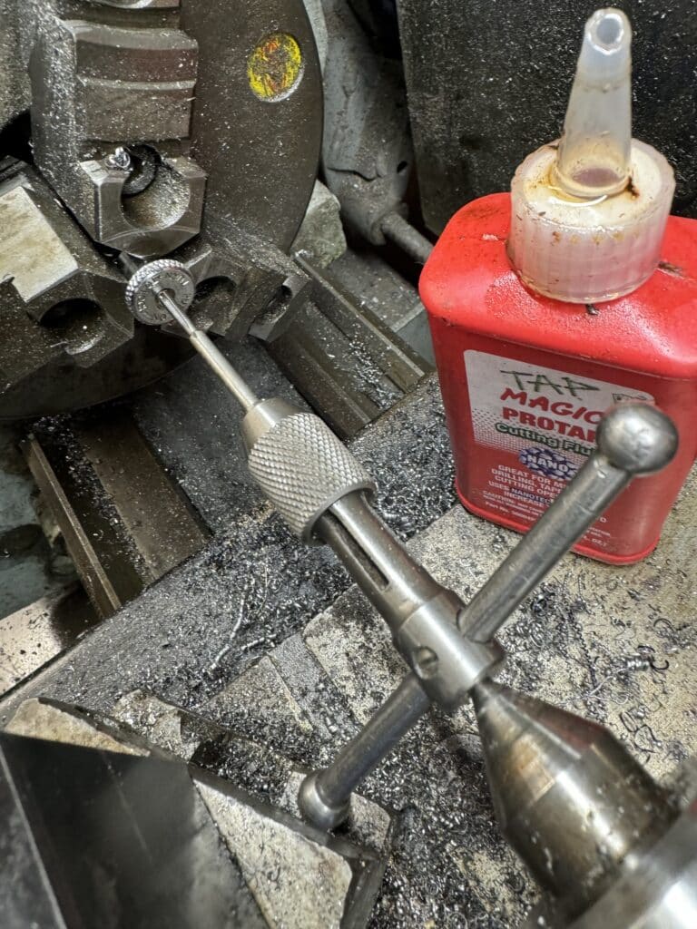
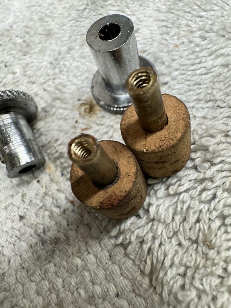
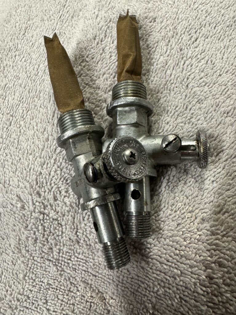
The push-pull fuel valve petcocks were also totally varnished up and a soaking in a container of acetone made them as clean as new. Since I was fairly sure that 60-year-old sealing cork would probably leak, we purchased new cork for the petcocks to insure a good seal. Even after steaming the new cork for 10 or more minutes, I was unable to make the cork supple enough to stretch it over the end of the shaft without splitting the cork. So I had to drill the rivets off the end of the shafts in order to remove and replace the shafts with new cork. Then I modified the petcock shaft by drilling and taping the brass shaft for a 4-40 stainless steel Phillips head screw to make the petcocks work like new. A small job that took a lot of time!
I sealed the petcock screw holes on the tank and protected the threads with 3/8” brass plugs. Then we mixed up the sealer and poured it into the tank. Using duct tape over the filler hole, I rotated the tank over and over in all directions, insuring that every part of the inside of the tank got covered with the thick 2-part epoxy sealer, top, bottom, front, back and sides. Since the instructions say there is enough sealer for a 10-gallon tank, we prepared Eric’s Trackmaster tank the same way and poured the excess sealer into his tank. His Trackmaster tank is tiny and the two tanks combined can’t be more than 3-1/4 gallons. Ten gallons is a stretch in my opinion, as we barley were able to coat both fiberglass tanks. By rotating the tanks every few minutes until the sealer set up, we got an even coating on the inside of the tank. We now have 2 tanks that are totally sealed and hopefully impervious to issues from Ethanol and other fuels.

Comments