
3/20/25
This post has been delayed because of issues we ran into installing valve seats. As with most procedures, there is a learning curve and especially for us since neither of us had installed seats before. BSA casts its steel seats into the aluminun head. They are round where the valve meets them, but have another shape at their base in order to be locked into the head when cast. Replacement seats are round and need to be tightly pressed into the head after cutting out as much of the old seats as possible. We need replacement seats for 2 reasons, First, the existing seats were cut way too low into the head for good performance and had groves in them that were wrong. Second, the intake seats were way too small to accommodate the larger 44mm valves we were using. We actually had to install seats twice because of our decision to use a cutting tool that didn’t work out as expected and we ended cutting the seats improperly on the first go-around. This was a time kill as the seats had to be machined out again, slightly wider and slightly deeper, then reordered and reinstalled. Once completed for the second time, we proceeded, avoiding the mistakes we made the first time around.
We decided to use modified Triumph bronze 6mm valve guides, since the Kibbblewhite guides are machined for and supplied with valve seals, and the BSA guides they sell are not. Both guides are the same outside diameter (OD) and come in several over-sizes, which we needed. We used 2 different OD’s for the proper fit of a .0015 clearance press fit. However, we had to shorten and re-taper the ends of the Triumph guides by .250” for the length and shape we needed. Not sure if we would have had to do this with the BSA guides, but we would have had to machine them to accept seals and purchase the seals separately. A trade off that worked out well for us.
Eric was able to find 6mm stem, 44mm generic intake valves. They have a long stem that needed to be shortened to the length we needed and grooved for the keepers. These are considerably larger than the stock 40.5mm intakes and also lighter with because of the small 6mm stem along with their head shape. They also came from Kibblewhite and all the valves are supplied with a “Black Diamond” slippery coating of some sort. The exhaust valves are oversized 6mm valve conversions for a Triumph at 38mm, up from 36mm stock, and are the correct length with the keeper grove already cut into them. We reamed the new guides to a slightly undersized 6mm and then honed each guide for a perfect fit.
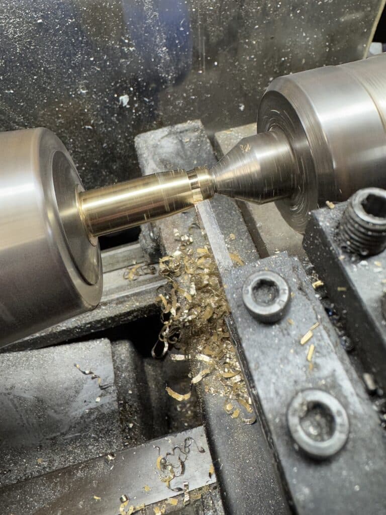
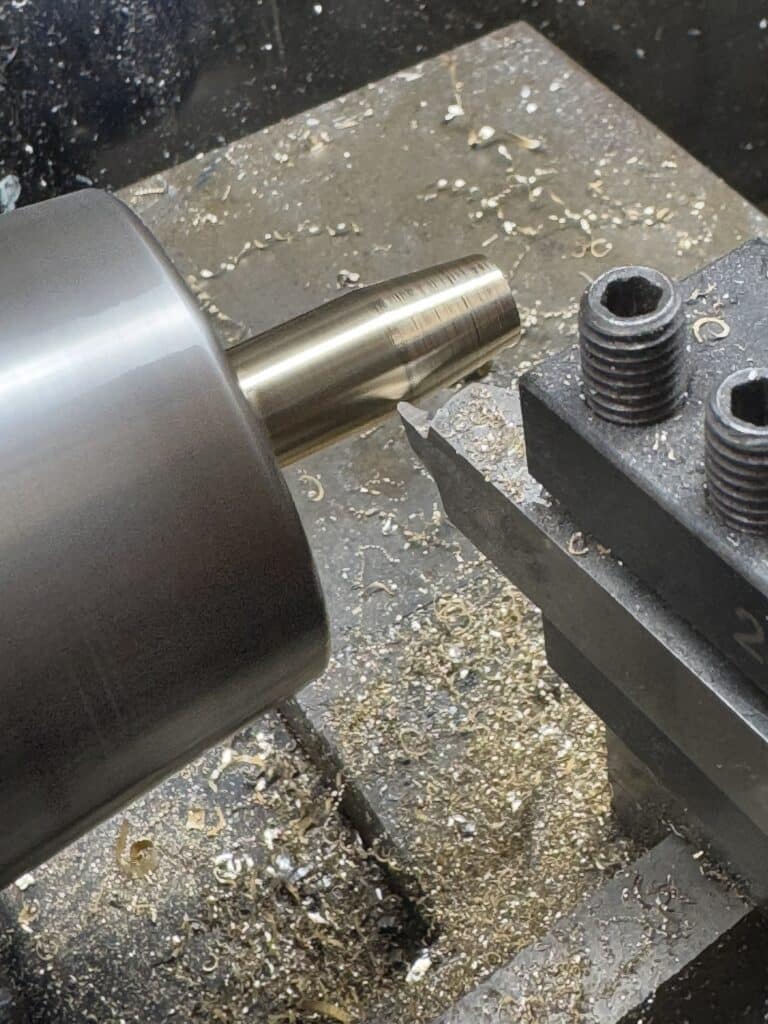
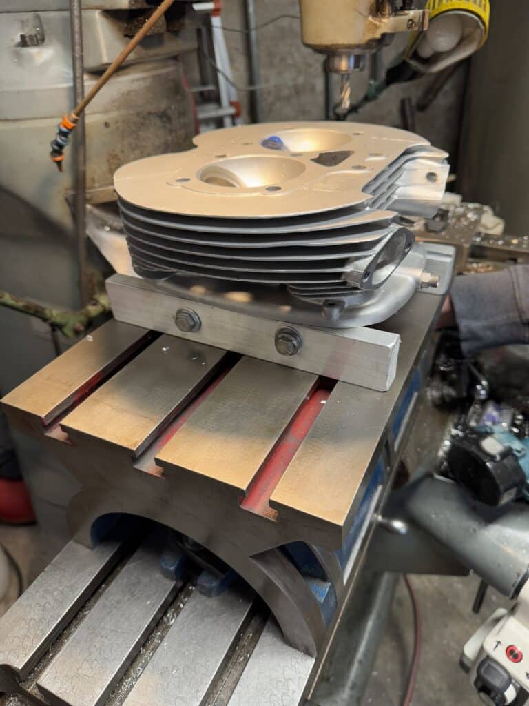
Next we set up an adjustable angle table I found on eBay and placed it on the mill table. Using 2 pieces of 1-1/4” x 3/4” aluminum bar stock, I made a pair of standoffs for the head to attach to the angle table. I set the angle table to 37 degrees and inserted a 6mm mandrel into the valve guide. The next part is where we made our mistakes. We thought, incorrectly in hindsight, that the single point cutter we used would only have to come close to the angle and center of the guide because we assumed the ball drive portion of the tool worked like a constant velocity or universal joint and would center itself when you got fairly close to the correct angle. It doesn’t! We thought this tool would save us from precision indicating each valve guide. It didn’t! We still needed to know if the valve seats cast into the factory head were large enough to cut the 5 angles we needed for the valve job. It turned out that they were not, so we had to cut out the old seats, order and press in new larger seats. This was scary, since the new seats had to be thick enough for a strong press fit, so the cut into the head for the new seats had to be fairly deep. This required cutting into the original seats without having the cutting tool “grab” the old seat and tear it out of the head. That would have required a lot of welding to repair, but we were successful here and the cast-in parts of the old seats are still in place, covered by the new seats . The same tool was used for this operation, but with a 90-degree insert in preparation for new seats.
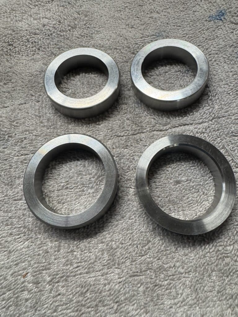
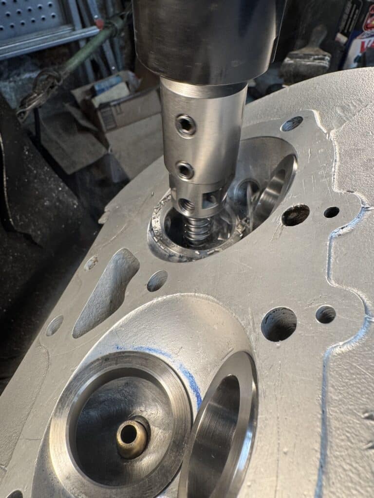
Cutting out the seats didn’t require extreme precision, just close as only the valve angle cuts required this accurate precision. After cutting out the old seats with this setup, we measured the 90-degree seat pockets for width and height, and ordered new seats from Tucker Valve Seats in Odessa, Texas. They are made from tungsten, alloyed with chrome, molybdenum and vanadium in a tool steel base, which creates an extremely strong hard alloy and are suitable with all fuels. They are far harder than the stock seats. Tucker machined them .007” oversize for a super tight press fit into the aluminum head. I made a driving tool with a center hole for a valve mandrel, to keep everything aligned as we drove them home. By heating the head to expand it at 300 degrees in the oven, and freezing the new seats with dry ice (-109 degrees F) to shrink them, we installed them with a large hammer and the tool I made. It actually turned out not to be very hard to drive the seats in with a .007” press fit. The dry ice shrunk the seats .002” and the heated head expanded the seat pockets .003”, so the actual press fit was only about .002” until the temperatures normalized. The white frozen seat can be seen in one of the photos below, beneath the driving tool, just before we drove it home.
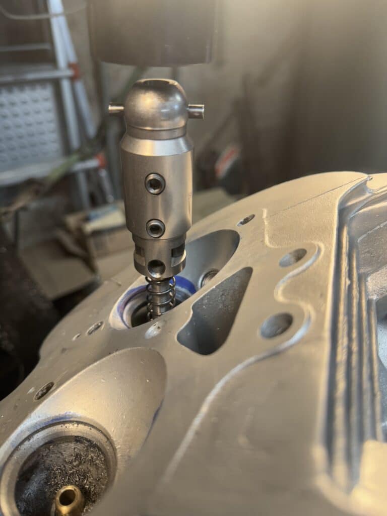
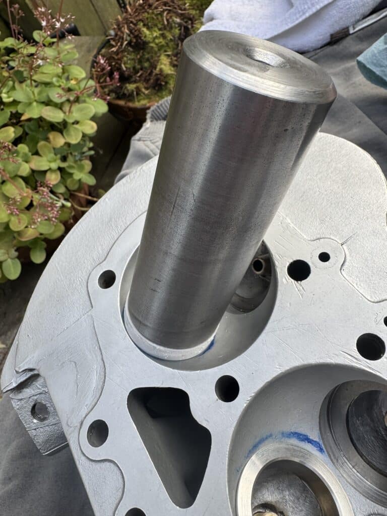
Frozen Seat Driven Into Hot Head
Once the seats were in place, we put the head back on the mill and using the angle table, we started the angle cuts for the valve job. This is where things went south on us.
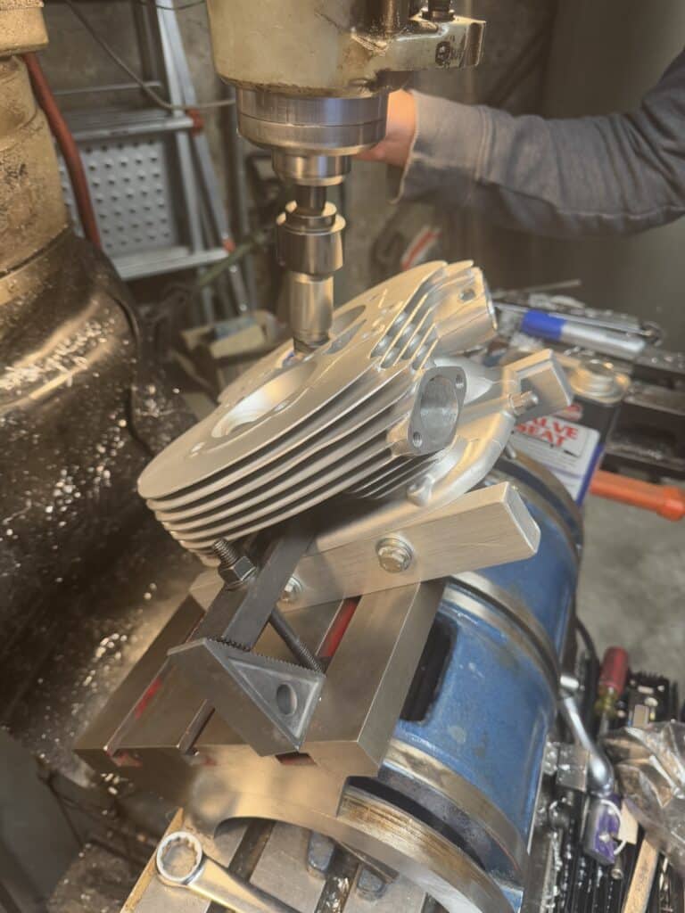
It was a straight forward machining process to cut pockets for the seats and press them into the head, but I grossly misjudged the cutting tool we were using. Since it had a ball socket attachment, I assumed it would self center, much like a CV or universal joint would do, saving us from dead accurate alignment of the valve guide with the quill of the mill. WRONG!!! As I have said before, never assume! Although the seats went in OK, the angles I thought would self correct with the ball drive did not. We cut the seats at a slightly wrong angle to the axis of the valve guide because of this assumption. In hindsight, which I am pretty good at, I should have gotten this tool holder with an R-8 Bridgeport adaptor, dialed everything in, and bypassed the ball end driver all together.
Attempting to salvage this, we correctly dialed in the head on the angle plate exactly in 2 axis with dial indicators and accurately located the center of the guide. This is a slow process and has to be repeated on each valve. We were hoping that with the mill zeroed in correctly we could salvage the new seats. This did correct the valve angles square to the seats, but by the time we corrected this mistake, the valves were set too low into the head for the air flow we wanted. This wasn’t a huge loss in dollars to re-order the seats, but the time lost in the do over in labor, shipping and general frustration was not what we wanted.
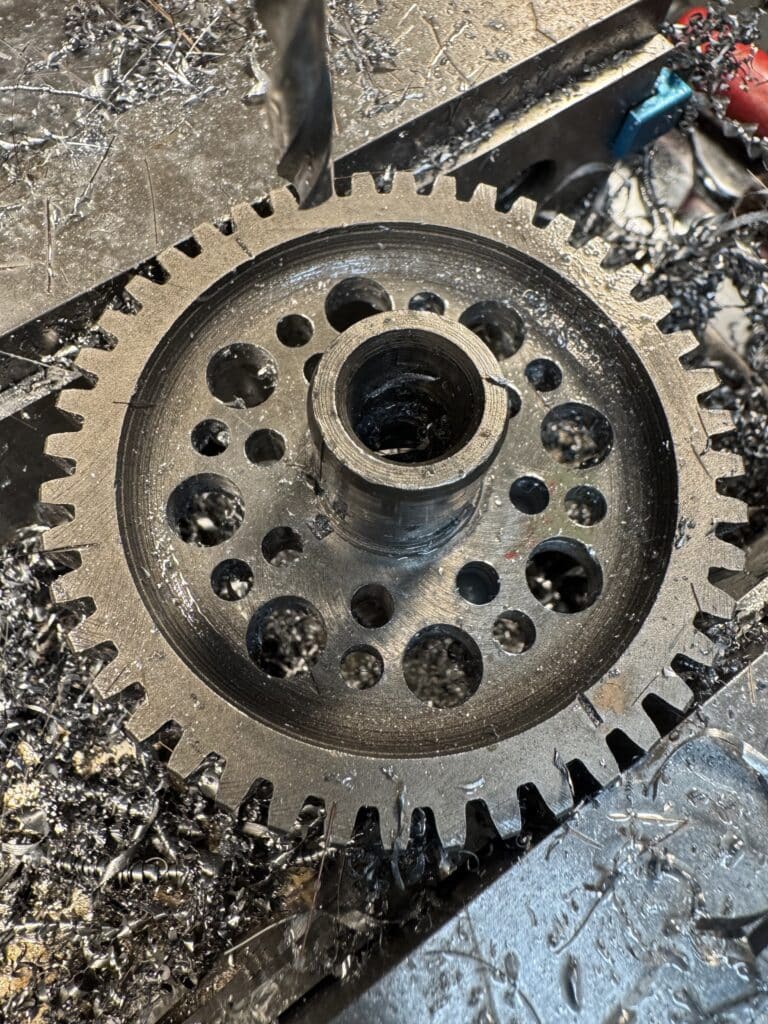
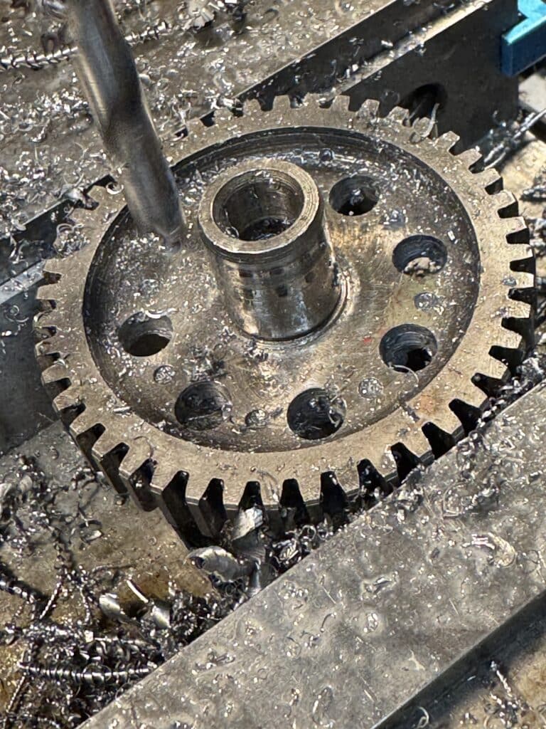
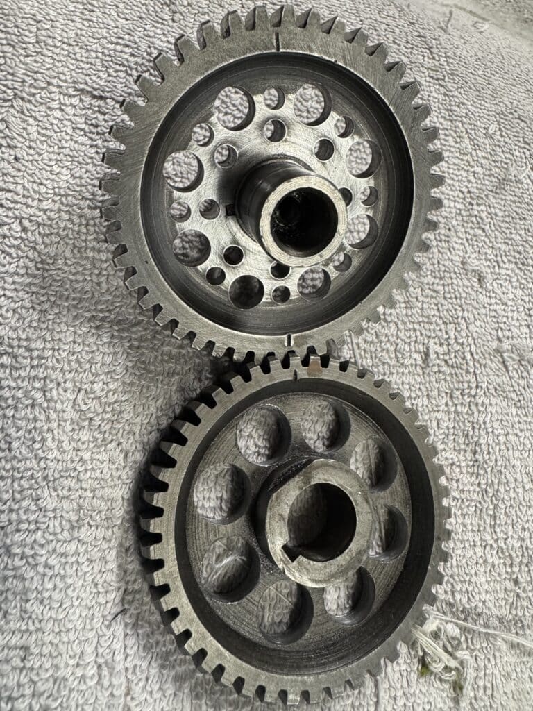
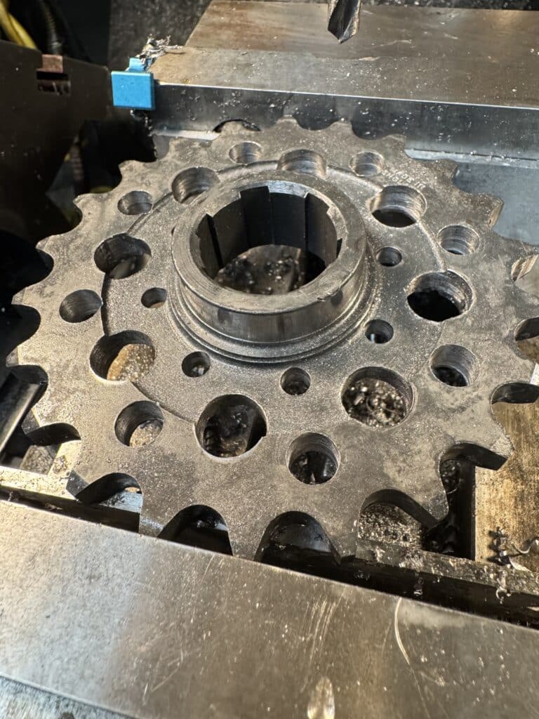
While waiting for the seats to arrive, we did a couple of small jobs to keep moving forward. To compliment the lighter valves, spring, and retainers, and using an indicator to find the exact center of gears clamped into the mill vice, we drilled out lightening holes in the timing gears using the mills digital readout (DRO). Every little bit of rotating or reciprocating weight we can save helps performance, and we also drilled the new 22-tooth main-shaft chain sprocket for some weight saving. Too bad none of this work can be seen once the covers are on the motor.
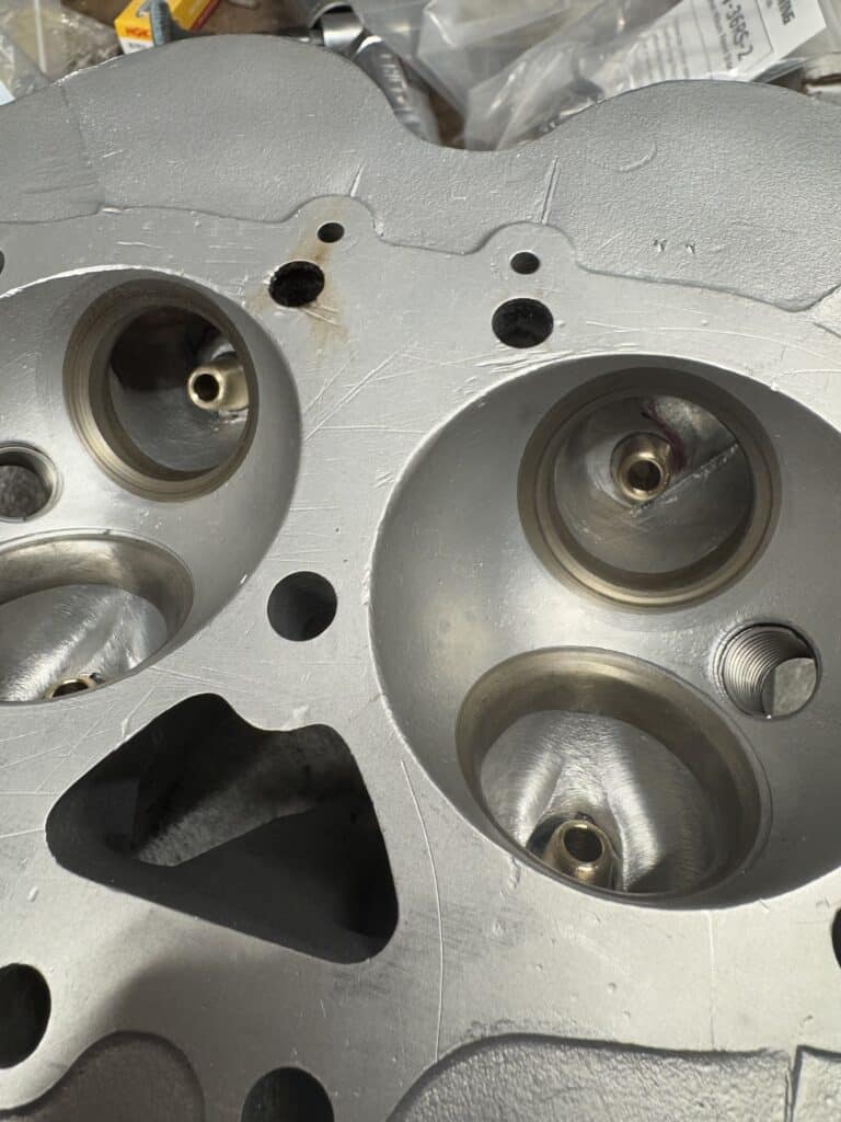
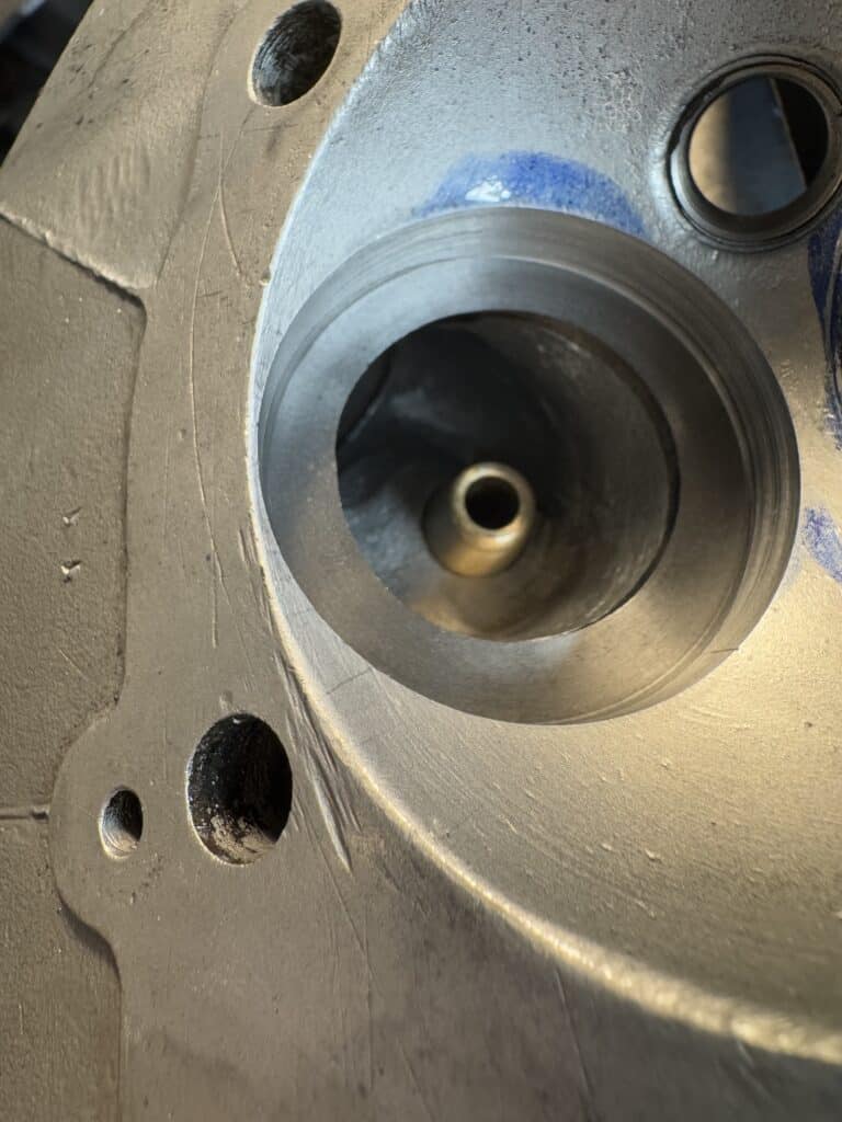
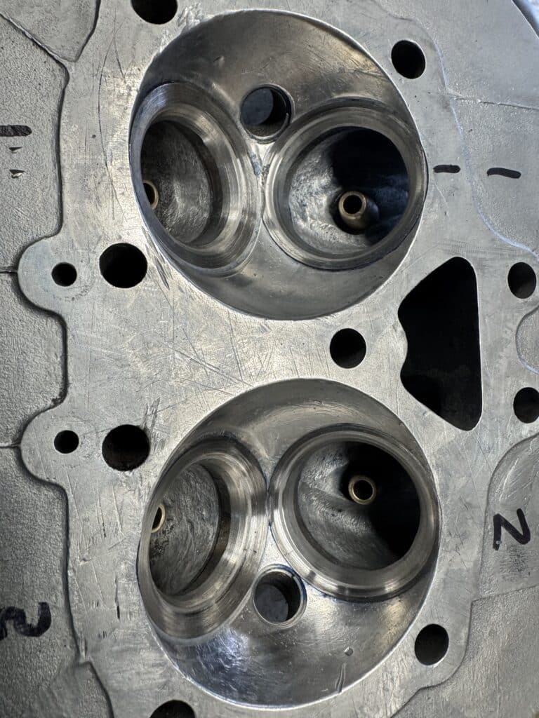
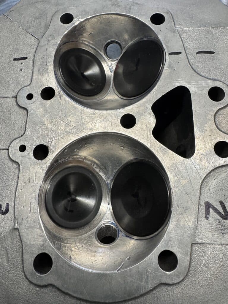
Once the seats were installed for the second time, we did hand grinding using a carbide burr in a die grinder to blend the bottom of the seats ID into the ported head. This was slow because the seat blending had to be done without changing the shape of the head from our previous porting work. Next, the seats didn’t quite fit the shape of the hemisphere in the head. The seat heights we ordered were all different, based on a measurement from the part of the head that was the lowest. This meant we would have to blend the outside tops of the seats into the combustion chamber by hand. Cutting the seats with a stone or other tool would have cut into the chamber un-evenly. This was something done at the BSA factory incorrectly in our opinion, as even after dialing in the valve guides in both axises, and accurately centering, the cutters did not engage the hemisphere of the head perfectly everywhere on the circle as one might expect. This is most likely why the stock seats and valves were set so low into the head from the factory. Again, this was yet another slow process.
Not wanting to repeat our first mistakes we went about cutting the seats with different methods. the first one was a bust, with a hand crank tool. It also had centering issues. We decided to use our Sioux grinding stones, as these self center on a mandrel placed in the valve guide. This was very slow on new harder than stock seats, so we decided to put the carbide cutting tools in a hand drill using a mandrel in the guide for a rough cut, to get us close. We would then finish with the stones for the final accurate cuts. This worked well, although very slowly until we figured out how deep to cut and in which order.
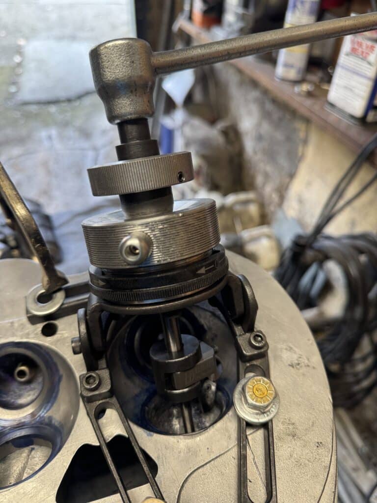
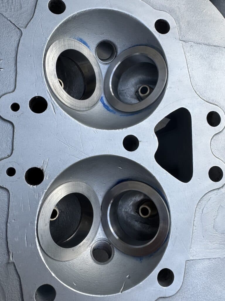
In the end we did it this way. First, we used a stone to grind a 30 degree angle close to the aluminum hemisphere of the cylinder head. This angle intersects the hemisphere fairly closely. Next, with blue marking dye, we scratched a line around the head of the valve we are working on into the seat. Then with a 70 degree cutter in the hand drill set over a mandrel and placed into the guide, we cut the seat until it came within about 1/16″ away from our scribed line. Switching to a 60 degree cutter, we cut to the same scribe line. We then switched to a 45 degree stone and ground the seat. This was the only angle that had to be exactly 90 degrees to the valve guide for a perfect seal. All other angles were for air flow only and and could be off a few thousands from concentric with the guide. Using fine valve grinding compound on the seating surface of the valve and using marking dye, we rotated and lapped the valve into the seat. Removing the valve allowed us to see exactly the wear pattern and the width of the interface of the valve to the seat as well as the location of the interface on the valve cut. When the width and placement were what we wanted, we moved on to the next valve. When complete, we had the valve job we needed the and had 5 different angles for optimum flow.
One last word about the tool we were attempting to use. I think it’s designed for a CNC machine and used with a fixture that the head would be placed into for repeated accurate cuts. Although a 3-angle cutter is available for this tool, it would only work well on a head that didn’t have new seats. There was just too much material to remove with the new seats and an exact dialed-in setup would be needed for a 3-angle cutter for each valve. Building a fixture for this purpose didn’t make sense to us in the beginning (or now) as using it for just one job made even less sense. Even for 2 or 3 jobs. If we were in the business of rebuilding 60-year-old BSA heads from a company out of business for 50 years for a living (ha ha — a sure money loser), and had orders for more than half a dozen, then a jig might be worth the cost and effort. I’m not in that business!
The head is not finished as far as this build is concerned. We still have to mill the head gasket face a few thousands.for a good flat seal, calculate and or adjust head and piston volumes for desired compression raito, measure and set up valve spring heights, and check for clearances between the valves and pistons at full cam lift, as well as clearances between the valves when both are open (overlap) at the end of the exhaust stroke and the beginning of the intake stroke. We wouldn’t be doing this if we had chosen to use a stock cam and stock valves, but without the correct clearances, this build could fail catastrophically. The motor will be assembled and rotated using a degree wheel to measure and get the clearances we need at different points of the rotation circle. Several tear-downs are possible because of this, and adjustments may be necessary to obtain safe clearances without parts interfering with each other. Different things can be changed or adjusted to obtain the minimum clearances we need. I’ll cover this in future posts.
amazing effort guys. love the detail.
Thanks Kevin, It’s actually fun…..when things go as expected!!!