
6/1/25
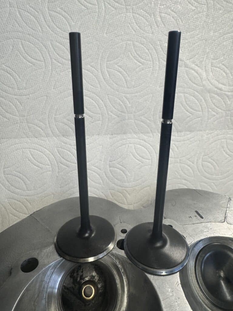
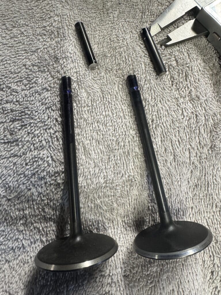
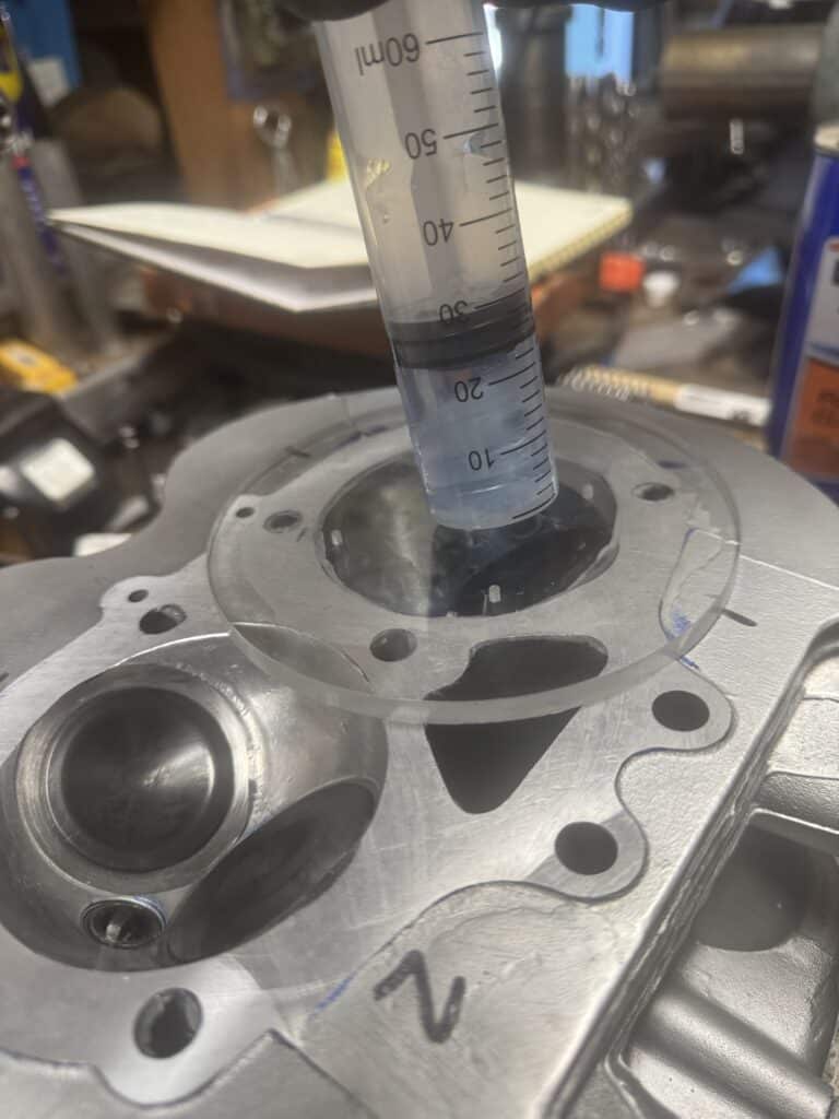
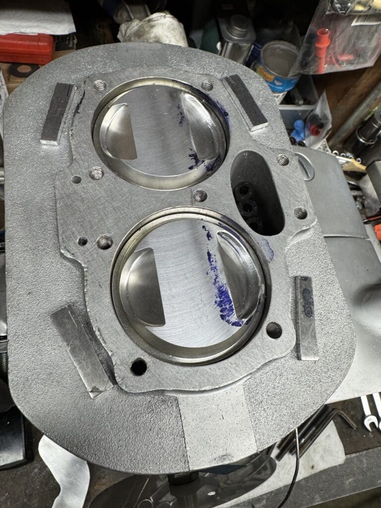
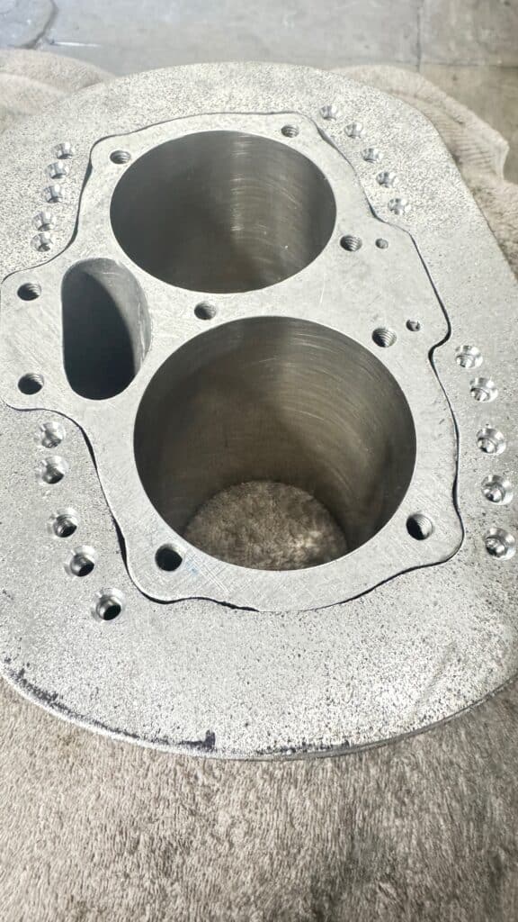
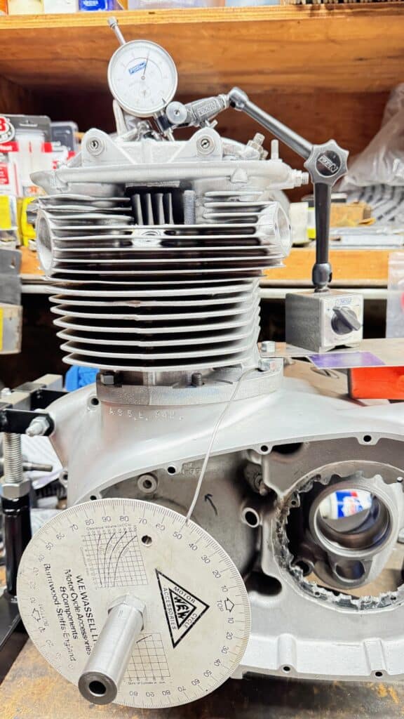
After many months of modifications, we are now able to assemble the motor to measure the compression ratio, check for clearances with the many new parts and see how everything works. The first thing we did was to cut the valve stems for the oversize 44mm generic intake valves to the correct length and groove them to install the keepers and retainers. Once this was done, I heated the stem tips to bright red and quenched them in water to re-harden the tips for use. We lapped and installed the valves in the head using temporary 15 lb. valve springs. Then we CC’d the cylinder head combustion chambers to check for equal volume, adjusting this if necessary. We used a lot of care and a depth micrometer when we ground the valves into the head, so we were happy when the volume of each combustion chamber was almost identical between the two chambers. Once completed, we measured the volume of the installed piston in the cylinder and plugged this information into a static compression ratio formula calculator available on the Internet. One needs to know combustion chamber volume, piston dome (or dish) volume, head and base gasket thickness, cylinder diameter, stroke, and with this information static compression ratio can be determined.
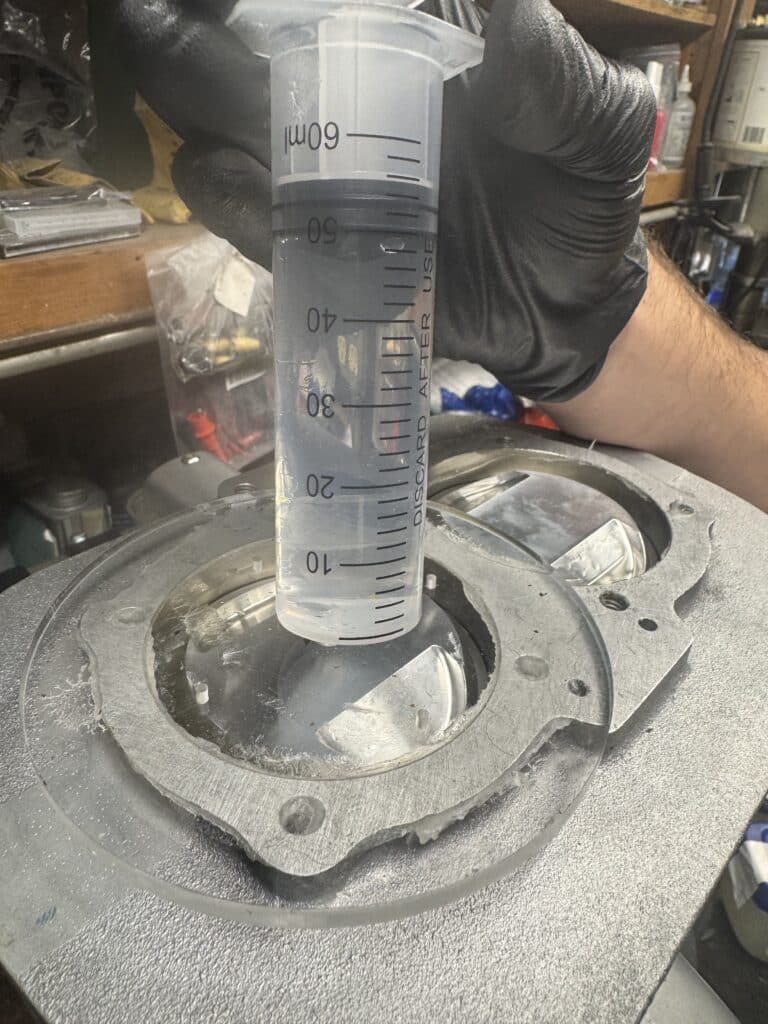
Placing a plastic disc with a hole drilled into it over the combustion chamber, and using a little Vaseline as a sealant, we can inject alcohol with a syringe to measure the cubic centimeters for the volume of the combustion chambers. Using the same plastic disc over the cylinder and measuring a fixed amount (in our case .500″ down from the top of the cylinder), the piston volume can be accurately calculated. Plugging this information into a formula available online gives us static compression ratio. We are attempting to end up with somewhere between 10.5 to 1 and 11 to 1 compression ratio. We ended up over 11 to 1, a little high for pump gas, but easily adjusted by using either a thicker base gasket or head gasket. This will bring the static compression ratio down to where we would like it to be.
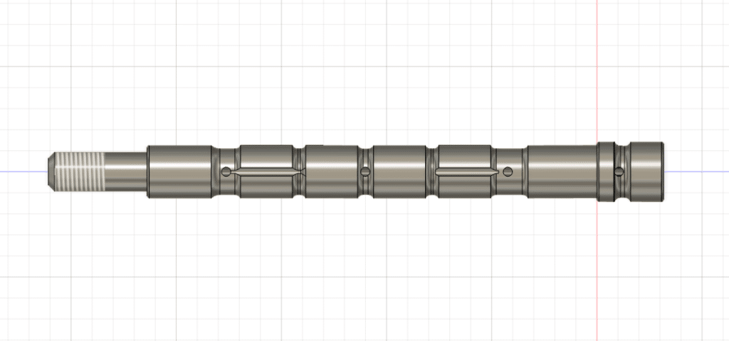
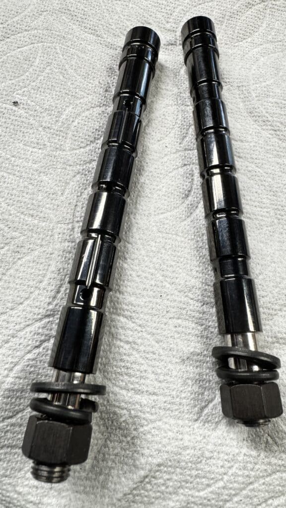
Using CAD, Eric drew rocker arm shafts that he sent out for machining. What he specified are made of tool steel and much harder than the original parts. He made some shafts for BSA and Triumph and was able to sell them almost instantly! The ones for my motor are finished with DLC coating along with the piston wrist pins, a super slippery and wear-resistant coating.
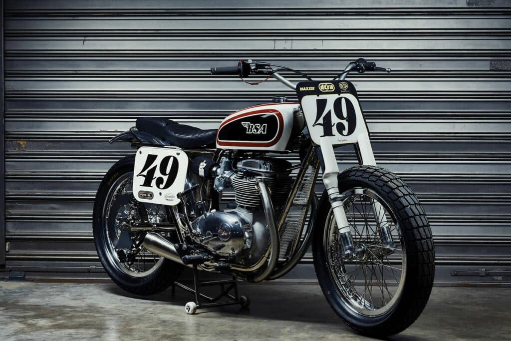
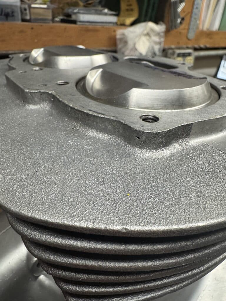
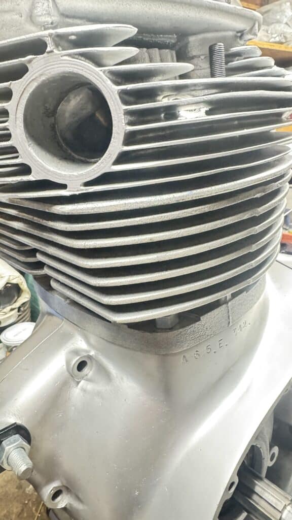
At this point I ran into a major issue, at least for me. Not a mechanical one but an aesthetic one. I originally wanted to install aluminum barrels on this motor when I saw a photo of a beautiful BSA with alloy barrels shown below (number plate 49). There were none available anywhere we looked online, but Eric found a guy (Ed Vee) that was importing some if he could get a minimum of ten orders. They were expensive, but I wanted my motor to look like the one in the photo, so I said OK.
We put our order in and were told it would be about 2 months for its arrival. After almost a year of waiting and many phone calls, it finally arrived, but I had to pay $300 more than the quote from the original already expensive order. Upon assembly of the motor for clearance checks, I was shocked to see what I had purchased. The barrels have a 3/8” rise above the top fin, which I didn’t think much about until I bolted the head onto the barrels and this gap became evident. What was this guy thinking when he designed these? This beautiful motor now looked like the Mona Lisa with her front teeth missing, in my opinion. What was worse, there is room for a top fin to fit perfectly in the space created, but it was left out! Spending this kind of money for something a first-year design student wouldn’t dream of doing was very upsetting, and after all this work it was something I just couldn’t live with. Worse yet, I couldn’t even think of returning the barrels, as the base bolt holes were not quite drilled correctly with the centers of the 8-studs that hold it in place. We spent a long time grinding the base bolt holes to get the studs to fit the misaligned holes, and once we did that, I owned it.
It turns out that these barrels are cast for a short stroke motor or a long stroke motor, BUT only look right on a short stroke motor. This wasn’t told to us in advance. For the short stroke motor, the top 3/8” is milled off the barrels and when the head is installed, it looks fine. The long stroke larger displacement version, which is what I ordered for the new crankshaft length, needs this additional cylinder height so there is a large gap underneath the cylinder head.
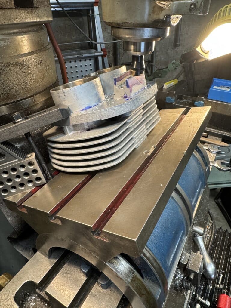
The fix was labor intensive, costly, unnecessary in my opinion, and would set us back almost another month. I ordered a 12” x 12” piece of .160” aluminum, the approximate thickness of the fins on the barrel, online since I couldn’t find that thickness locally. Then, taking the head and barrels off the motor we had just assembled and using a thin piece of cardboard, I traced the outline of the barrels onto the cardboard and made a tight-fitting template for a new fin. The issue at hand was two-fold. First, I had to make the smooth aluminum plate look like the rougher casting of the barrels. Second and far more worrisome was how to attach the fin. Welding would be the obvious choice, but welding heat moves metal around because of warping. These barrels are already finished bored with a piston clearance of .002”, which left zero room for error.
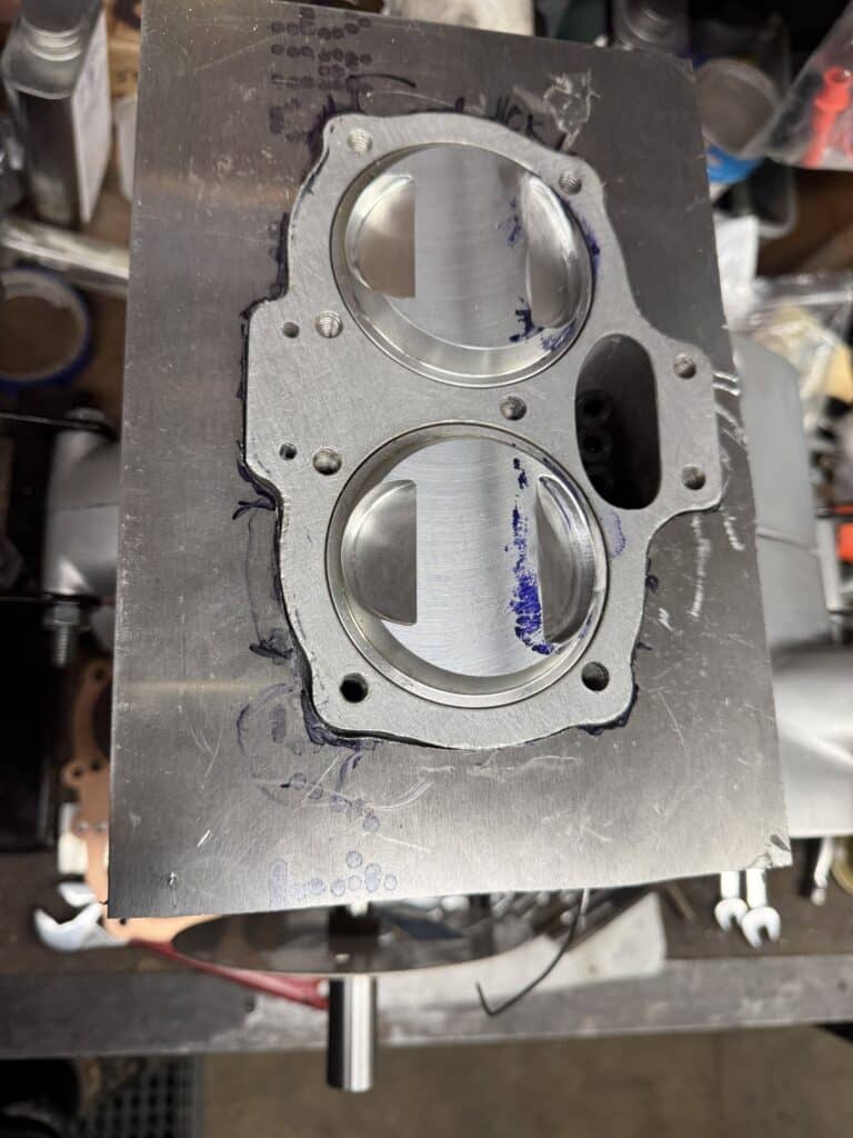
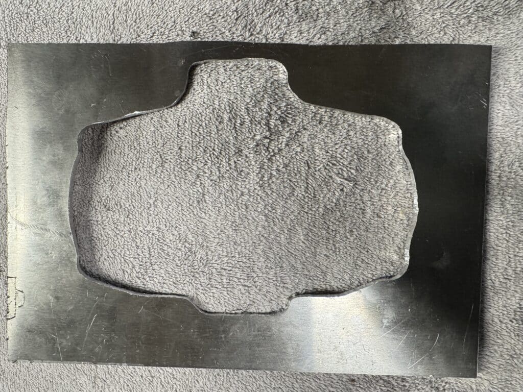
The new fin finish was obtained by using a 36-grit sanding disc and tapping it into the fin with a smooth faced hammer to transfer the sandpaper “grain” onto the new fin. The only part of the fin that can be really seen is the edge of it and maybe about ½” deep. I will take my newly made part and the barrel over to Shawn Campbell https://www.instagram.com/narleyfab/ so he can then vapor blast the outside of the barrels to match the finish of the rest of the already vapor-blasted motor.
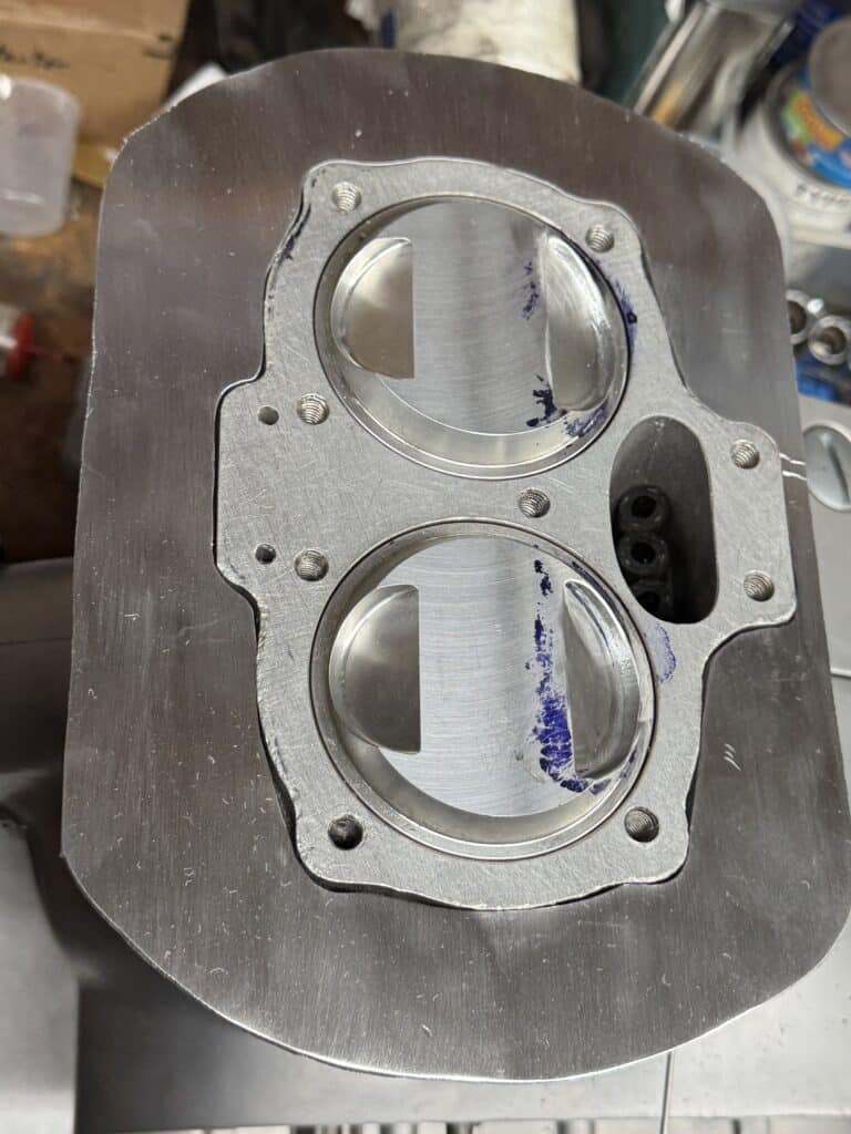
I made some standoff pieces out of the same thickness aluminum to place on top of the original fin and positioned the new fin with the proper spacing. I used JB Weld, an extremely strong heat and oil restraint epoxy (up to 550 degrees F) that actually is impregnated with metal to glue the standoffs to the existing fin. I will ultimately use JB Weld on top of the standoffs and set the new fin down into the glue on the standoffs. I will also apply another application of JB Weld, this time squeezed into the small space around the circumference of the cylinder and the new fin. When finally completed, there will be a 360-degree “weld” between the new first fin and the original (now the second) fin.
I used a tap drill to drill 20 holes through the new fin, through the standoffs, and into the second fin. Then I tapped threads into the standoffs and second fin, and countersunk these holes in the new fin for stainless steel 1/4 x 28 x ½” flat head screws. I want the screws not because the JB Weld wouldn’t be strong enough, but because I will be able to get some heat transfer from the existing fins to the new top fin. JB Weld is a plastic epoxy and even though it contains steel particles and is slightly magnetic, it is an insulator of heat. With the addition of the screws, this should change this and actually make the new fin somewhat functional, as well as fixing the aesthetic issue. The screws won’t be seen unless the head is removed. The finished result looks good and should hold up well. I will assemble the new fin after everything is vapor blasted.
The whole fin issue could have been easily avoided if the top fin had been added to the casting pattern before casting the barrels. This would be relatively easy to accomplish, since the pattern is made from wood, which can be glued and shaped easily as opposed to what I had to do. It also would be repeatable for many cylinders. The barrels would then look correct for a long stroke motor, and by cutting off the top fin on a band saw before milling the barrels, would work correctly on a short stroke motor with one less fin.
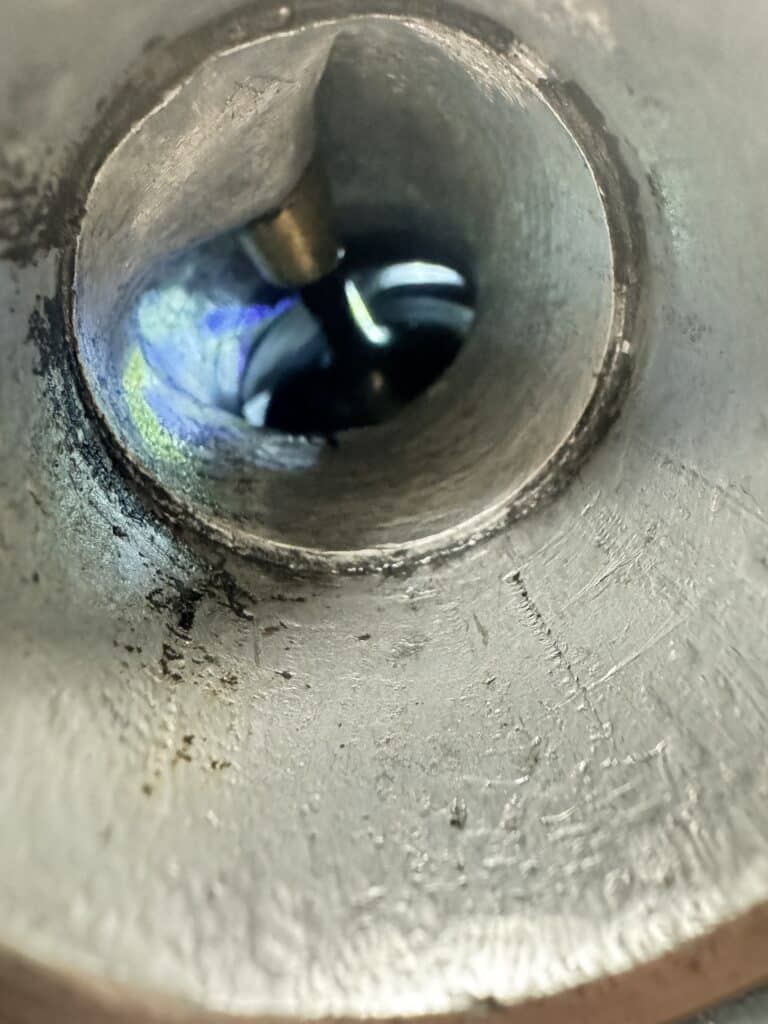
Now we could reassemble the motor again and without the timing gears installed, the new camshaft would not rotate a full circle. We loosened the cylinder bolts and added a .030” series of shims and that gave us clearance for rotation. By removing shims, we discovered that the camshaft just rubbed the cylinder barrels at the tappet block with .012” of clearance. We needed a total of .060” clearance to be removed from the cylinder tappet block and using our adjustable angle table, we milled off the cylinder for the clearance we needed.
After assembly, the cam rotated freely with good clearance, so we installed the timing gears, cylinder head and push rods. As I attempted to rotate the motor, another interference was found, actually two. The new slightly larger exhaust push rods were rubbing on the cylinder barrels, but also the larger 44mm intake valves were hitting the piston tops very close to top dead center (TDC). Taking the motor apart again, I used a die grinder to take a small amount of metal off the barrels for the push rod clearance.
By holding the pistons in in the mill vise with small vee blocks, we tilted the head of the mill to match the angle of the piston valve relief cutout. Using a boring head, we enlarged and deepened the piston valve notch for clearance and also went from a .040” head gasket to a .060” thicker gasket for more clearance. Upon reassembling the motor, we were now able to rotate the full circle and using clay in the valve relief notch of the piston, we were able to measure the clearance by measuring the thickness of the clay. Of course, this required removing the head to get to the clay and checking to see if we had at least the .070” we wanted.
The thicker head gasket and piston notching of course was lowering the compression ratio, so we had to re-measure the cylinder volume again with the modified pistons. The static compression ratio is now at 11 to 1.
The final clearance we needed to check is for safe clearances between the valves during cam overlap. This check was to measure the space between the partially open intake and exhaust valves using carefully a short-bent round rod of the correct clearance diameter. Looking through the exhaust port with a mini flashlight fit into the intake port, we could measure the distance between the valve heads. We want a clearance of at least .050” (we were told that .040″ was absolute minimum clearance). The valves actually slightly rubbed on the first try, so we went back to stock sized 36mm exhaust valves from the 38mm that would clear the intake valves. This gave us clearance for 360° rotation, but not enough for safe rotation at 8,500 plus RPM’s. By re-grinding the exhaust seats a few thousands of an inch and lowering the valves slightly into the head, we gained a little more clearance. We now had about .044” clearance between the valves, not quite our goal, but closer.
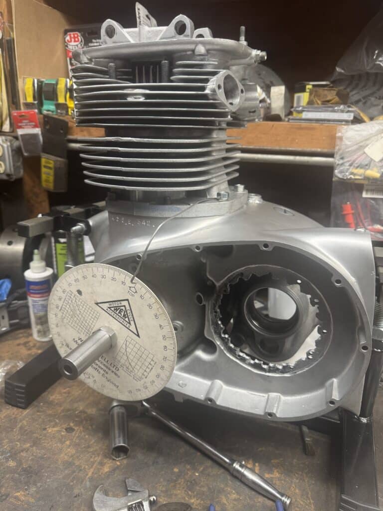
At this point we needed to time the camshaft to the specifications on the cam card supplied with the new higher lift, longer duration camshaft. Timing the camshaft would change the valve clearances we were working on so this needed to be finalized first. This was accomplished with a degree wheel on the crankshaft and using a dial indicator to precisely measure the valve opening and closing (at .040” lift as stated on the cam card) for intake and exhaust valves in crankshaft degrees. Our measurements were then compared to the numbers on the cam card. It turned out we were off from the cam card, and we needed to adjust the cam timing to bring the cam into spec for optimum performance.
I phoned Jim Dour, the cam grinder at Megacycle Cams www.megacyclecams.com, gave him our data and he calculated we would have to retard the camshaft 6° to bring it into spec with the cam card. This is accomplished by milling an offset in the keyway on the camshaft or crankshaft which would then position the crankshaft gear 6° retarded. We decided to use the offset keyway on the crankshaft rather than the camshaft as access is a little easier.
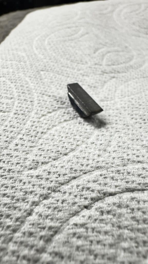
We had to figure how many thousands of an inch offset would be needed to be cut into a woodruff keyway to retard the cam 6 degrees. To accomplish this, we measured the diameter of the crankshaft at the keyway where the gear fits, multiplied by π (3.14), and divided the answer by 360 (degrees in a circle). That gave us the answer for 1°, so we multiplied this times 6 and came up with just under .036” offset for the 6° we needed at the crankshaft gear to retard the cam to closely match the cam card specifications. On the mill, I cut this .036” offset into a piece of steel and we ground the bottom of the key to fit the shaft. An amazing amount of time spent for such a small but important part.
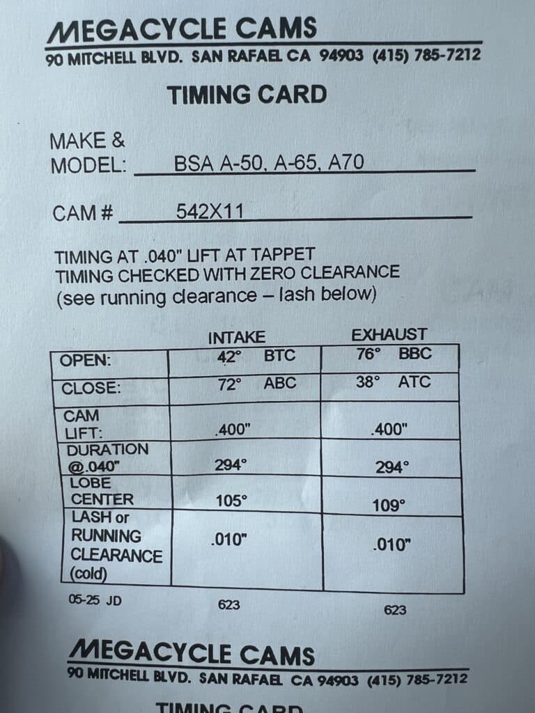
When the new offset key was installed in the retard position, it brought the cam timing into close agreement with the cam card, and also increased the valve clearance at valve overlap to about .052”. The intake valve now opens at 44° BTDC and closes at 72° ABDC. The exhaust valve opens at 79° BBDC and closes at 40° ATDC. These numbers did retard the cam 6° from our original numbers and we are now closer to the numbers on the cam card. We ended up with 104° intake and 109.5° exhaust lobe centers, very close to the specs on the cam card. This is about as close as we could expect since intake and exhaust lobes are both on the same cam and can’t be timed separately like on a Triumph with separate cams.
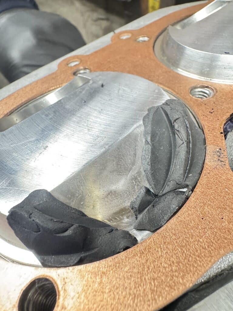
We painted the tank with SprayMax 2K Rapid Primer Filler – #SPM-3680031, which got a final sanding with 400 grit paper before the color coats. I picked House of Kolor Stratto Blue ll 0403, and 66 Auto Color Paints, https://www.66autocolor.com in Joplin MO, put it into rattle cans, SprayMax SPM-3682072. It’s a semi-translucent blue that’s sprayed over a silver paint coat from a 1960’s Chrysler/Imperial, also SprayMax, SPM-3682071 (K3 Sunbeam Silver), which highlights the pearl and metallic. We ordered some BSA Hornet vinyl transfers that Eric drew up and scaled to size, and put them on after the blue paint and the first coat of clear was applied. We sanded the clear coat with 1,200 grit wet sandpaper. The tank was sealed with several coats of clear SprayMax 2K Clear Glamour sealer, 386 0061, with repeated sandings until the BSA transfer could not be felt. SprayMax 2K Clear Glamour sealer is also gas & fuel resistant and brings out the color really well.
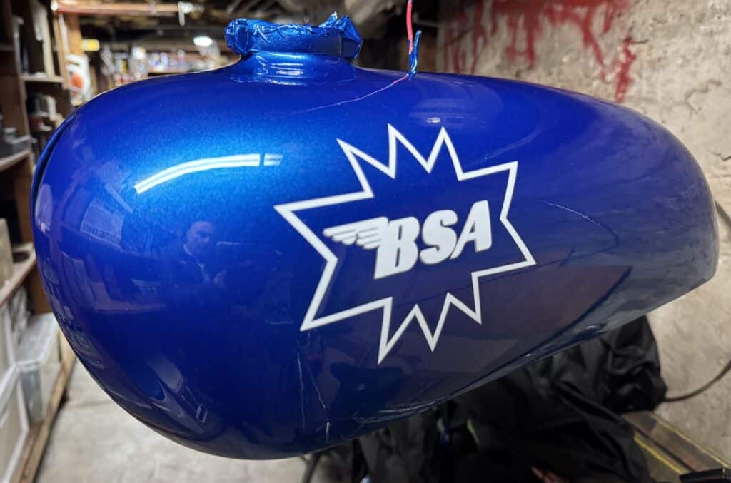
All in all, the work on the tank was a long process with a couple of re-do’s, but the end results look fantastic. Painting in a San Francisco garage as winter approaches had its challenges and now that it’s warmer again, I’m glad it’s behind us. Eric did most of the paintwork, and I did most of the preparation, including the fiberglass repairs. Now that the tank is lined inside and clear-coat sealed outside, we shouldn’t have to worry about gasoline and Ethanol sitting in the tank any more, or fuel spills on the paint. To limit gasoline spills, I cut out a new neoprene gasket to replace the rock hard one in the Monza cap so it should seal well. Along with rebuilt petcocks, we should be all set.
Comments