
9/10/25
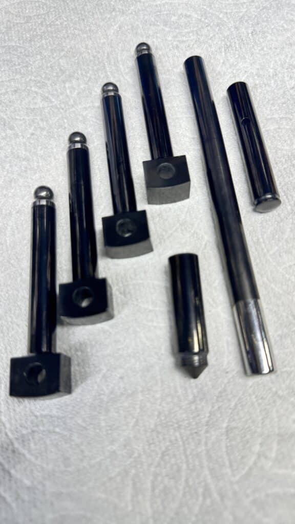
We are getting close to the final assembly, and this effort has kept us fairly busy. Most of our time has been spent on getting ready to ship the rotating and reciprocating engine parts out to be dynamically balanced. Eric has also had some parts machined out of very tough and hard tool steel, namely the rocker shafts, cam lifters (followers), shifter shafts, and detents. The rocker shafts and lifters are nowhere near as hard as they should be in stock form and almost always need re-surfacing or replacing at rebuild time. His new parts should change this as well as reducing friction. He sent the parts he had made out to be coated by a process called DLC (Diamond Like Carbon), which greatly reduces wear, and is very slippery as well. DLC coating, along with polishing the transmission gears and shafts should make this bike shift very smoothly. The new wrist pins were also DLC coated for less wear and less friction.
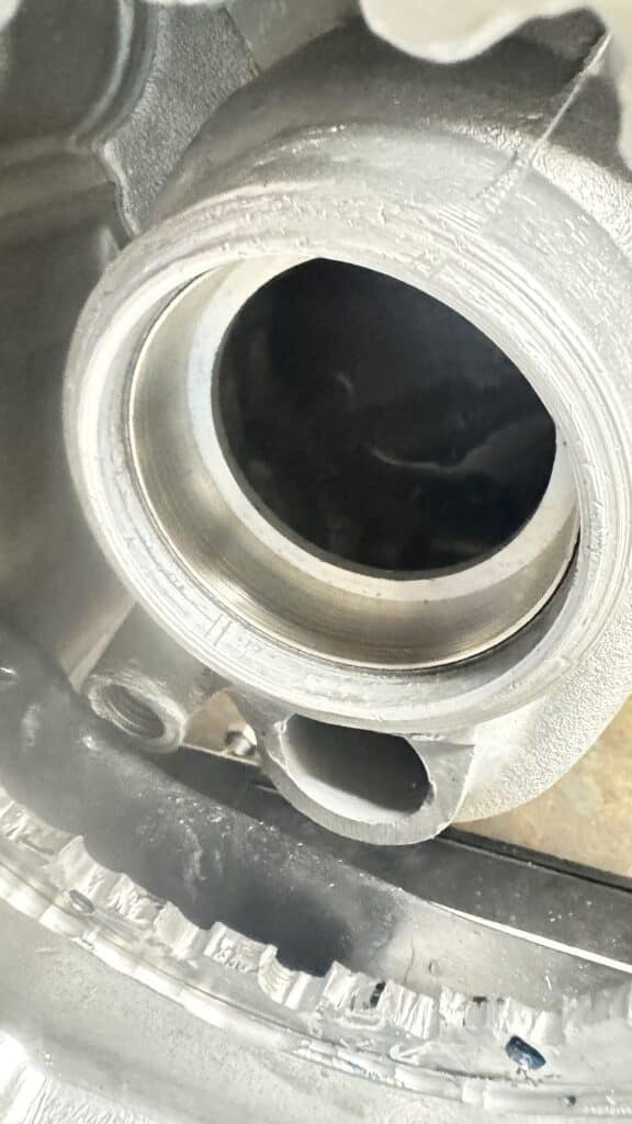
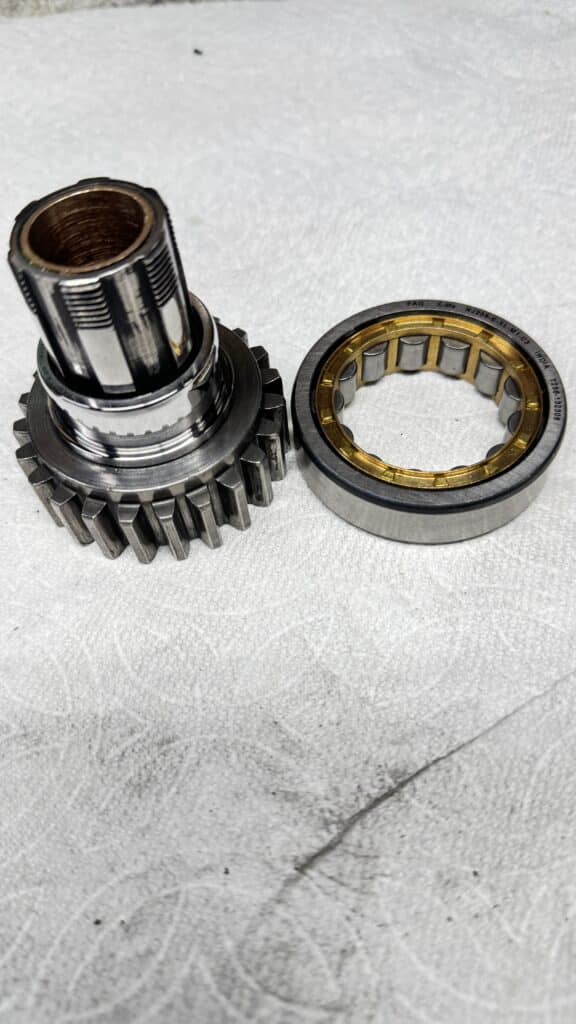
Also, at the last minute, I decided to change the transmission main shaft ball bearing to a more robust roller bearing. This required setting the case on the mill, indicating the existing bearing bore to find the center line, boring it deeper by .005” for the slightly wider new roller bearing. Then I turned a spacer on the lathe to press into the case to capture the new slightly smaller diameter (about .060”) new roller bearing. Next I turned down the inner race (also about .060”) of the new bearing to press onto the transmission main shaft. Now, the only original ball bearing left in the motor is the timing side of the transmission, and a ball bearing is needed here for thrust purposes. The new outrigger bearings in the clutch trap door and the crankshaft extension are both ball bearings, but these 2 bearings take a secondary load.
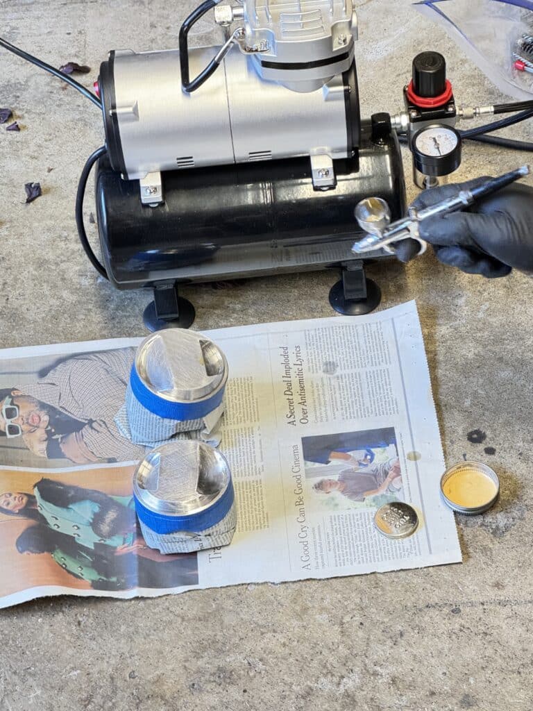
All the brass or bronze bushings for the camshaft and the transmission, as well as the rocker arms received a coating from Tech Line Coatings that Eric sprayed onto the bushings with an airbrush and we baked in the oven for 1 hour at 300°F. The piston tops are coated with a gold thermal barrier that lets the engine run cooler by transferring heat away, and the ability to reduce pinging from high compression. The same gold coating is applied to the combustion chamber, both valves, and the exhaust port for heat transfer. The sides of the pistons are coated with a dry film lubricant, which holds oil and reduces wear, friction, galling, scuffing, and both coatings are baked in the oven with the same process.
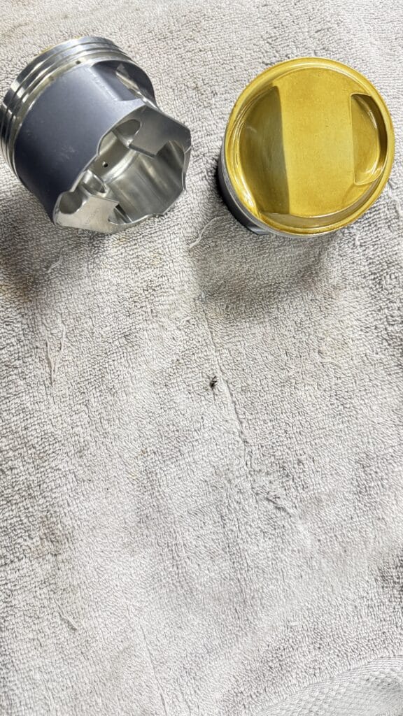
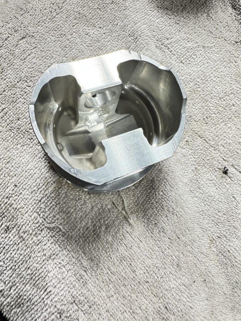
We had two sets of 80mm pistons. When I started this project, I originally was going to sleeve some BSA barrels out to 80mm, so we purchased a set of JB 80mm forged aluminum pistons for this purpose. We sent them out to a guy who lightened the undersides of them on a CNC mill. But when I decided to purchase aluminum barrels, I found they came with 80mm JE pistons as well. In fact, they were the same part number piston as our original pistons, except the wedge tops of the new pistons were milled down to lower the compression ratio. The first set would have been well over 14 to 1 compression and would need to be cut down also for our use. In order to for either set of pistons to work with the new larger 44mm intake valves and the higher lift cam, we needed to enlarge the intake valve pocket in the top of the piston and deepen the pocket about .070”. We did this to the pistons that came with the new barrels and milled them to work for our needs.
So now these pistons had the clearances we needed for the valves and we wanted to send them off for CNC milling on the underside for more weight savings, i.e. less vibration. Unfortunately, the man who CNC lightened the first set was seriously injured in a drag racing crash and went out of business. Trying to find a shop that would lighten them for a reasonable price proved hard. The CNC set-up requires enough time that it isn’t worth the money for just a pair of pistons. 50 sets would have been cheap, one set was expensive. So I decided to mill the wedge off the higher compression pistons that were already lightened on the underside and enlarge and deepen the intake valve pockets to meet our needs. When finished we had a second set of pistons that were almost 40 grams lighter than the set without the CNC work.
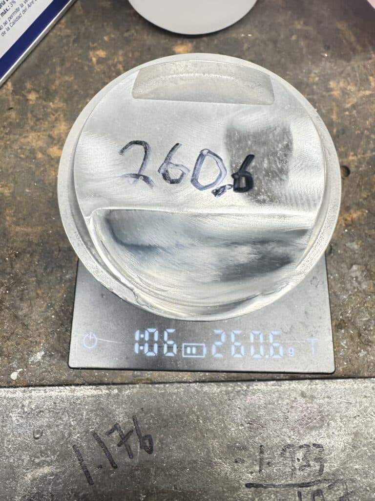
The last step before balancing was to equalize the weight of the pistons as close as Eric’s digital scale would read. By careful milling and constant checking we got both pistons equal at 260.6 grams each. At this point we coated the tops and sides and sent them off to Revco for balancing.
I searched for a while to find a really good engine balancing shop and found a great one in Long Beach, CA, Revco Precision Balancing and Specialty Machine who did a fantastic job. They will balance anything that rotates, from driveshafts, to automotive racing, marine, electric motors, etc. I wanted a shop that didn’t drill the crankshaft counter weights to remove weight where needed to bring the crank into balance, but rather, would cut or grind the flywheel and rotating parts to bring them into balance. I shipped the crank, rods, bearings, pistons, pins, circlips and rings in a heavy well-packed box and a couple of weeks later everything came back fully balanced. Twin cylinder English motorcycles vibrated like crazy back in the day, so lighter pistons and a good dynamic balancing is a must. For anyone interested, the balance factor ended up at 69%, plus 9.5 grams per throw for oil. Total bob weight was 681.1 grams per throw.
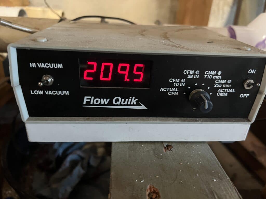
Measuring the airflow through the intake ports was the next project until we got the parts back from Revco. For this, Eric has constructed a flow bench to measure the volume and speed of the air flowing through the intake port in the head at a given valve lift. He is using a vacuum pump to suck air through the heads intake port and measuring the flow with a mass air sensor from a sensor he found at an auto wrecking yard, and several pressure sensors. Flowing the head shows us the improvement over a stock un-ported head as well as enabling us to make adjustments to each intake port for a balanced flow. When calibrated correctly, a flow bench will be able to tell us how our flow numbers compare to other BSA twins as well as other British twins like Triumph’s and Norton’s.
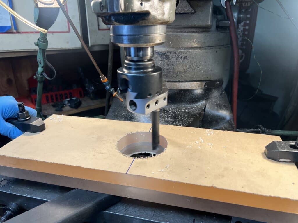
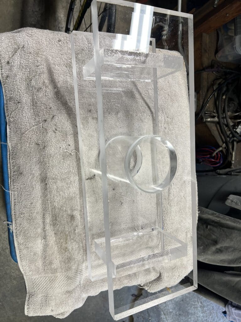
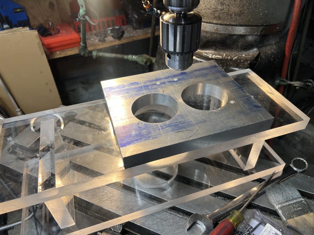
Building the flow bench has been an interesting project and Eric has done most of the work. He made a clear plastic part that has a 4” tube glued in between the 1” thick top and bottom plastic plates. He will use a different size tube to slide into the 4” fixed tube in order to match the bore size of the motor he is flow testing. It’s an 80mm sleeve for my motor but a differently bored motor will get a matching sleeve. To get perfect alignment with repeated accuracy, we took a piece of 1” aluminum plate, bored 2-80mm holes into it with the exact spacing of the BSA cylinders, drilled and taped it in 4 places for some 3/8” all thread to screw into the aluminum. This allows him to slip any BSA heat onto the flow bench and using a 1/16” neoprene gasket to seal the head to the bench he gets perfect alignment and a perfect seal. Three more holes drilled into the aluminum plate and plastic top allows the head to be repeatedly indexed from one cylinder to the next with accurate results every time. We will make a different aluminum plate for each brand of motorcycle we flow.
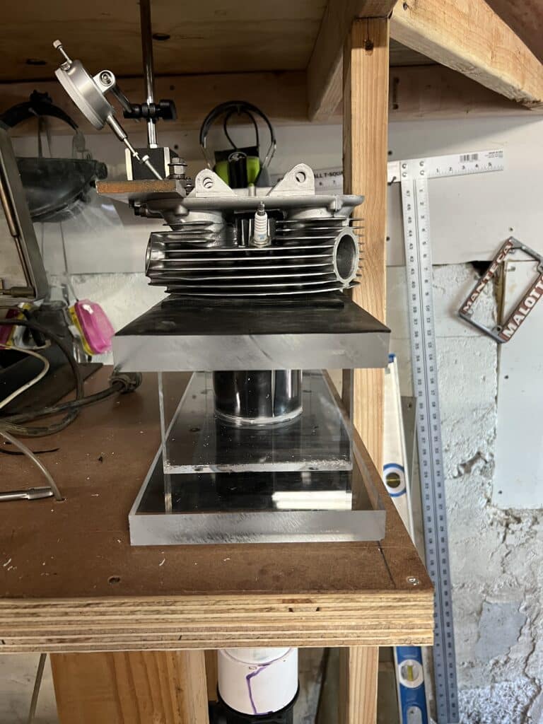
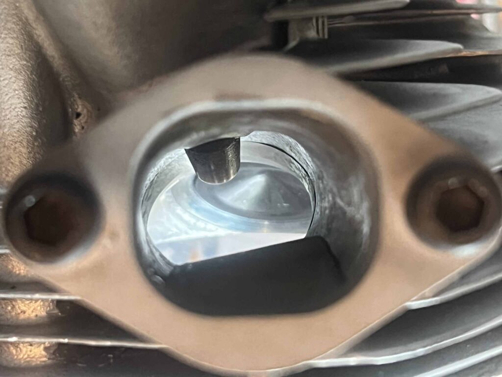
Eric didn’t have a flow bench when we started the porting so we have no “before” figures to compare the improvements. The 1964 Spitfire Hornet had 27mm round intake ports. Sometime a few years later, BSA went to 29mm round intake ports, but still used the same head casting. We enlarged the ports to an oval shape, 34mm wide. Using a fixture Eric made that holds a dial indicator with a threaded shaft, he can open the intake valve to set increments. Eric has a BSA head from the last series of BSA’s made in 1971, a 750cc A70. It’s also 29mm, totally stock, and when he flowed this head on his flow bench, the flow was 120 CFM (cubic feet/minute) at .500” intake valve lift. For comparison, our ported head flows at 209 CFM, at .500” valve lift. 209 CFM is 1 CFM away from the maximum flow with this 44mm intake valve and 5-angle valve job. However, we are using 3D printed aluminum port floors that increase the air speed while reducing the volume slightly. The air speed is more important than airflow volume. With port floors installed, the volume of air drops to 189 CFM at the cam’s peak lift, but the air speed greatly increases. The combination of the air speed and airflow we get is directly related to the horsepower at the rear wheel and with the airflow numbers we are getting, should be close to 100 HP. A dynamometer session in the future will tell us the whole story!
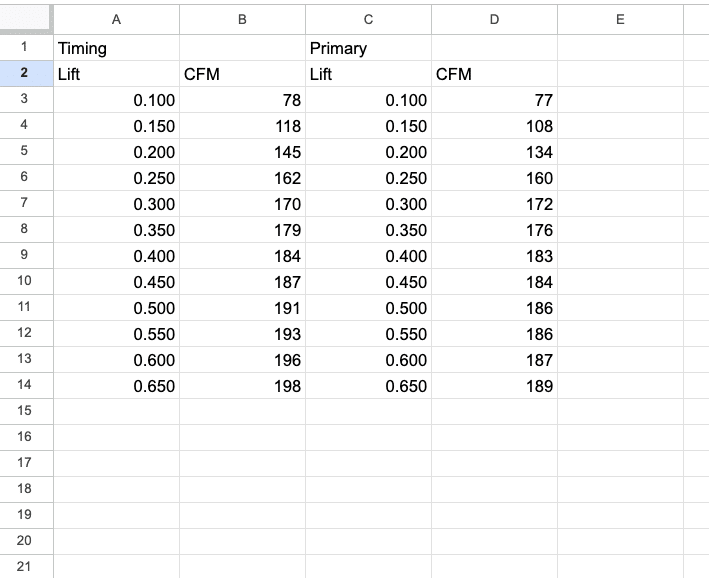
The chart below shows the airflow with the floors installed in the intake ports of both cylinders. The “Timing” side is the right side and the “Primary” side is the left side of the motor. Typically, flow is measured at .500″ lift for CFM, but our cam lifts to about .450″ so this is the number we are most interested in. We are not going to touch the Timing side, but Eric is going to tweak the Primary port to try and even them out.
In the near future Eric plans to get an article up detailing the specifics around the flow bench, but in the meantime, everything is now ready for assembly and my next post will show this.
“Constant attention to detail is the price to be paid in the pursuit of excellence”, I stole this phrase from a car restoration magazine and decided to keep it as my companies credo, remember, “all work and no plagiarism makes for a dull story”! I also stole this line from my friend David Cheppa, he also has many other quotes that he wrote like: “Marriage is like a midnight phone call, first you get the ring, and then you wake up”, also: “relationships feature the arcane art of emotional macrame, they come with strings attached”! Thank you again for keeping me informed about this incredibly detailed motorcycle project! Larry, please see the following: YouTube search: “howtohomelife” (16-videos), and “JBL Synthesis creator” (2-videos).