
10/29/25
Even though Eric and I thought we had worked out everything needed to do before assembly I knew there would be issues along the way. We weren’t disappointed! Some parts had been fitted several times during modification and went together as planned, while others took a little tweaking, and some a lot of tweaking.
The cases had been trial fit so many times I expected no trouble with them. We did a final cleaning of the cases, cleaned the oil passages in the crankshaft after balancing, and installed the camshaft in the timing side case. Using a thick assembly lube on all rotating parts, we torqued the rods bolts according to Map’s instructions. Next we placed the crank and rods into the drive side case, cleaned with acetone the mating surfaces and coated them with Hondabond sealer. We lubed the cam with assembly oil and placed the timing side case onto the mating side, and torqued the case bolts. Then we installed the new SRM drain filter and plug on the bottom of the motor. Now we could turn the motor 90°’s and place it in the stand for continued assembly. The crank and rods spun so easily with the aligned roller bearings, even with the thick assembly lube. All good so far.
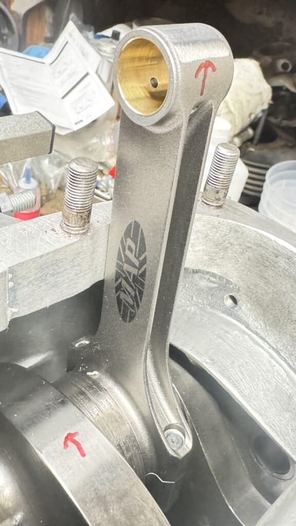
I installed a circlip to the inside of each piston where the wrist pin goes and then installed the rings. I placed the pistons over the rod and pushed the wrist pins into the piston, through the rod, until it stopped at the inside circlip. Then I stuffed clean rags around the rods and into the cases to keep the circlips in check as I installed them onto the outside part of the piston. JE Pistons use a very difficult type of circlip to install. They are just a piece of spring wire with no hole at either end for a common installation tool. I spent quit a bit of time, finally with 2 more hands from my wife Nancy, to get them in place. We also spent quite a bit of time looking for them as they shot away multiple times in the process, but finally got them installed. I thought about changing to the more common circlip type along the way, but the engine had been balanced with these and JB pistons come with them, so we fought them on until we succeeded! The red arrows point to the areas where Revco ground the rod ends and crankshaft for balancing, without having to drill holes.
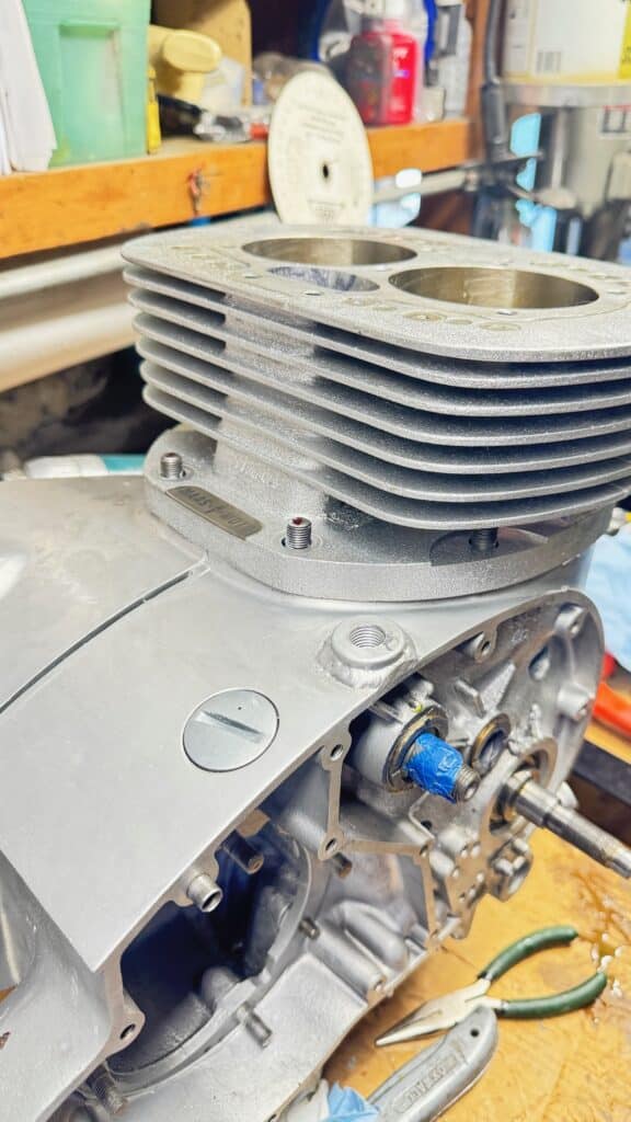
I lubed the cylinder walls, lubed and installed the tappets into the barrels, and placed a large radiator clamp over each set of rings as a ring compressor. Using acetone again to clean the top of the cases and the bottom of the barrels, we placed the base gasket over the pistons and case studs and again sealed everything with Hondabond. Using a piece of wood with a cutout for the rods, I rotated the crankshaft until the pistons sat firmly on the wood. I used short pieces of rubber hose over the end of each tappet to keep them from dropping down into the case as we installed the barrels. Nancy held the barrels over the pistons as I gently tapped the barrels down over the pistons, loosening each hose clamp slightly until the pistons were fully in the barrels and I removed the hose clamps so the barrels could drop down all the way into the cases and we could install the nuts and washers over the studs.
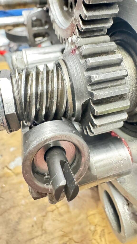
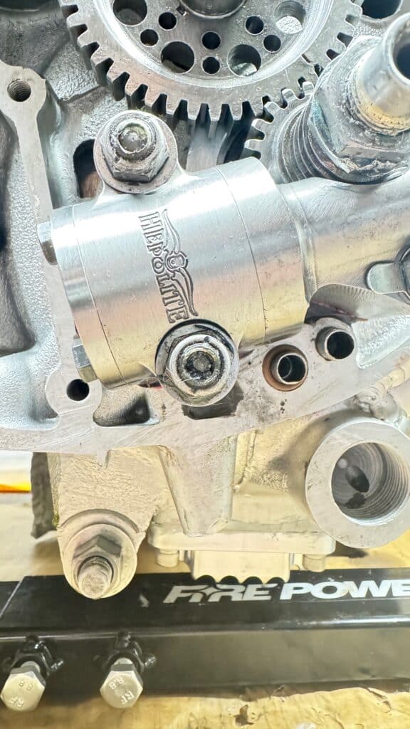
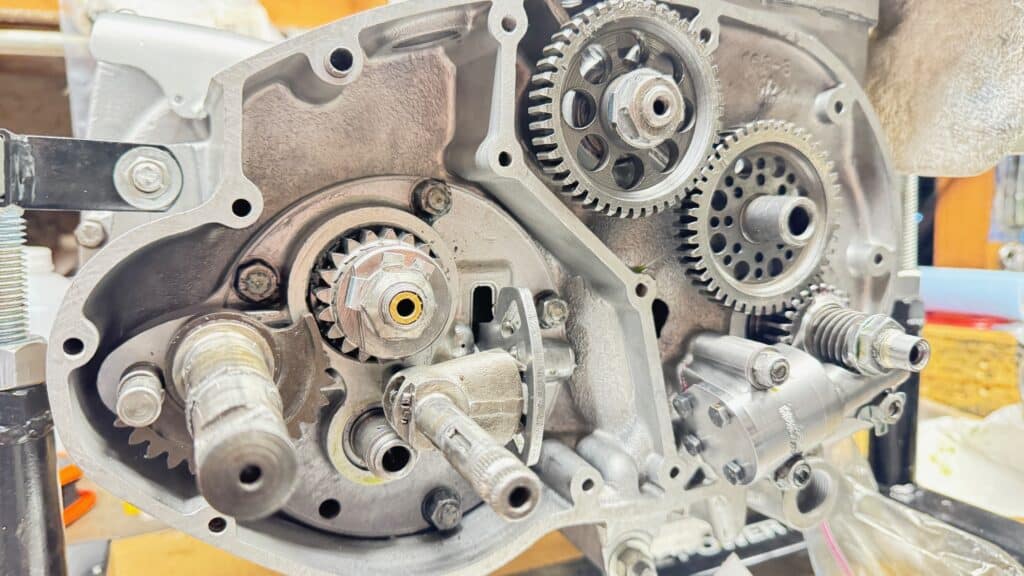
Then I removed the rubber hose pieces over the tops of the lifters so they could now drop down onto the cam, installed the crank gear, cam gear and intermediate gear, aligning all timing marks. Using a piece of hard wood, I jammed the gears in order to torque the cam nut down using blue Loctite and bent over the locking tab. The first small issue came up when I placed the worm drive LH worm drive nut with its washer, lock tab and LH jamb nut on the end of the crank. The motor never had this washer in its previous build and I became concerned that its .060” thickness might interfere with the oil seal or circlip from our modified crank end oiling system. I fit the new Hepolite high flow oil pump onto the studs to check how its worm gear aligned with the worm drive nut and saw there was ample clearance to shorten the worm drive by .060”, the washer’s thickness. Now I was sure the end of the crank nuts would clear the oil seal with is circlip.
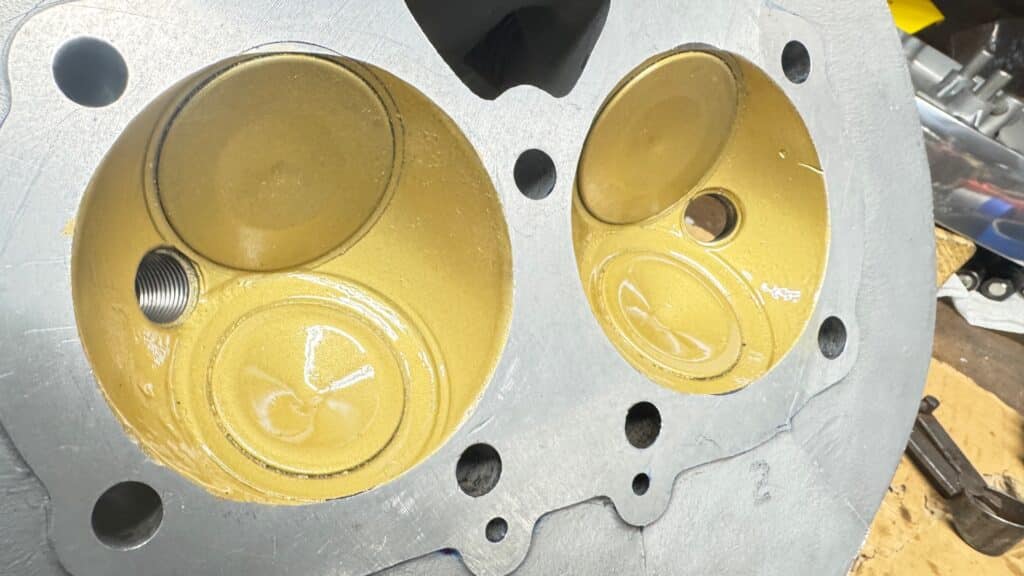
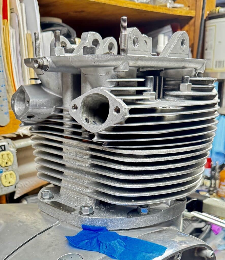
We coated the head gasket with a sticky copper coat sealant and also brushed it onto the top pf the cylinder barrels. The cylinder head went on next and was torqued down to 30 lbs. It will get re-torqued again when the motor goes into the frame and then again after it is run for an hour or so.
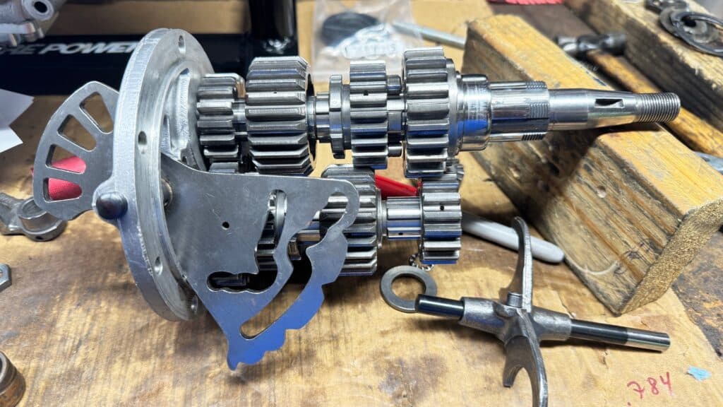
The next job was installing the transmission. First, we replaced all the bearings and circlips. In order to check the thrust clearance on the countershaft, the entire transmission has to be totally installed dry and then the countershaft endplay can be measured with a dial indicator. I measured .020” and specs called for .002” to .005”. Pulling the transmission out and replacing the special hardened thrust washers with thicker ones on the countershaft was accomplished, correcting the clearance. They come in three thicknesses, and I needed a combination that would add roughly .017” to my total. I calculated which of the three sizes would work best and headed across the Bay to Mean Marshall’s to get the sizes I needed. They were expensive for flat washers, but he had what I needed. I once again lubed the new bearings with assembly lube and installed the transmission, hopefully for the final time. I then installed the starter shaft and gears and the shifter shaft. After re-torquing everything and making sure the bending lock tabs were bent, we were ready to install the inner timing cover and transmission.

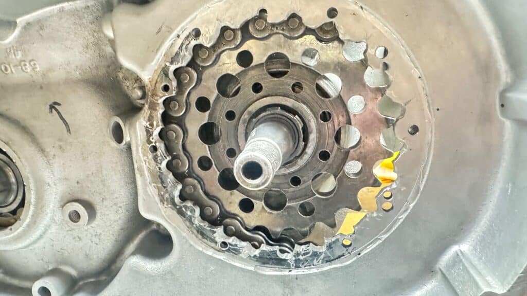
Sliding the engine stand around 180° gave me access to the main shaft where it came out of the transmission on the drive side through the new roller bearing. All looked good so I trial fit the new larger 22-tooth chain sprocket and wrapped my old chain around it to check for clearance against the steel chain guard I had made. None of this could have been checked until the transmission was installed. The clearance was 1/4” maximum as near as I could see, possibly less, but nothing was rubbing so I removed the chain and sprocket in order the install the oil seal. British bikes leak oil. Some of it is from the wrong gasket sealants available back in the day, some from vibrations, but some of it is by design (or lack thereof). It’s said that if a British bike isn’t leaking, it’s out of oil. It’s an uphill battle, but we are trying to fix this. One source of leakage is the splines coming out of the transmission and the crankshaft. Although there is an oil seal, it only seals its mating part, but not the spline. My “fix” is to use acetone and several Qtips to thoroughly clean the shaft spline and the inside of the 22-tooth gear mating spline. Placing Hondabond all over the shaft spline, I slid the sprocket with its spline onto it and into the oil seal. Again using Hondabond on the spline on the other side of the sprocket, I slid the splined locking tab in place and installed the 1-1/2” nut over this gooey mess, torqued everything down and bent the locking tab. I cleaned up as much excess sealer with Acetone as I could, and installed the drive chain once more to check for clearance. We were then ready to move on to the next step.
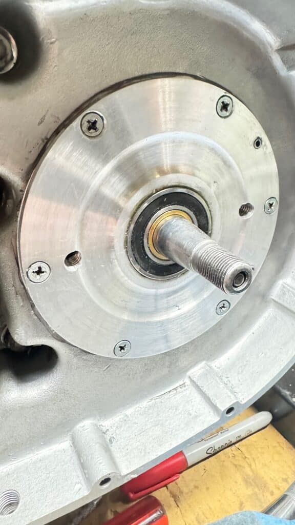
Another thing I was unable to check until all of the above steps were taken was the clearance between the large nut and the bearing on my new outrigger trap door. I was very close, only separated by a few thousands of an inch. So I cut out a spacer of .062” aluminum sheet and made a large “washer” to space out the trap door into the primary case. This gave me clearance, so using Loctite on the six screws I installed the trap door onto the case. The old trapdoor didn’t have a bearing for support, only an oil seal which I don’t need now that I’m using a dry belt-drive clutch. The new outrigger bearing aligned perfectly, so at least here, the care we took previously had paid off.
Now it was time to install the new Bob Newby belt drive clutch. It is a gorgeous part and machined beautifully. Almost. Since there is no adjustment like with a chain drive, the crank sprocket, geared belt, and clutch basket have to go on at the same time as one unit. After installing the crankshaft seal and spacer, using Hondabond on the spline in the same manor as the transmission spline, I placed the drive sprocket, belt, and clutch basket on each of their shafts. The spline on the crankshaft was very tight as it should be, but when both pieces were driven home, the clutch basket did not sit on the taper well. Tapers are supposed to be an interference fit, very precession, very tight, and usually needs a puller to remove them. This fit was sloppy for a taper and would not stay on the shaft. When I pushed the clutch basket as far as it would go on the taper with the belt on it, the belt was out of alignment with the front sprocket by about 5/16”. I was immediately suspect of the taper on the clutch basket hub.
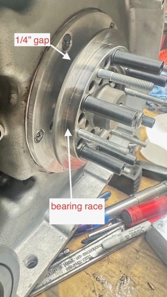
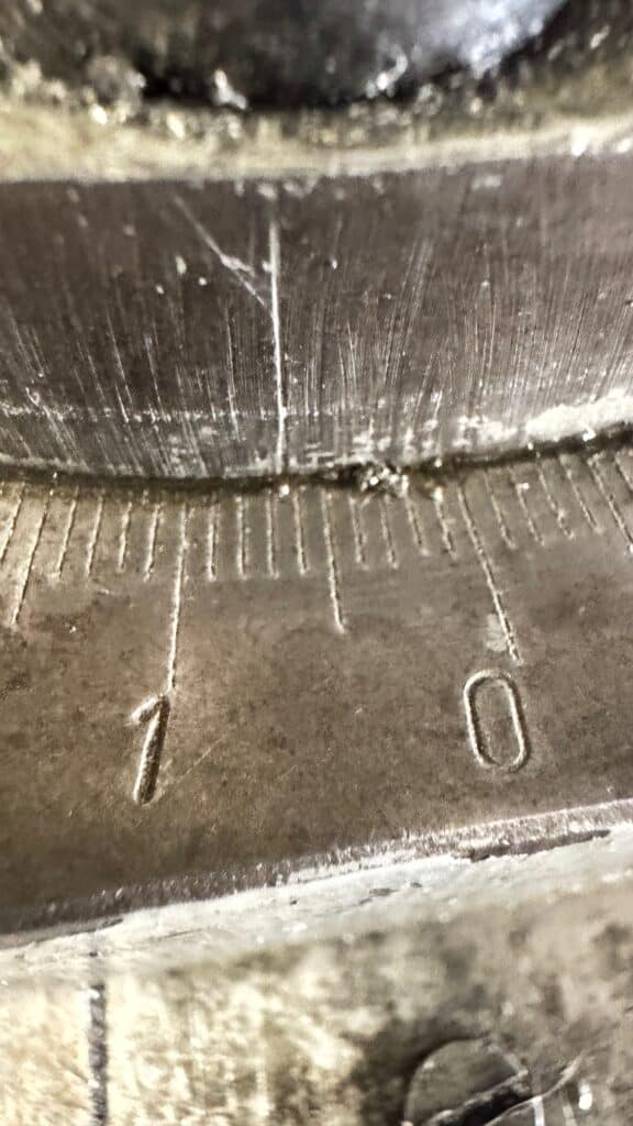
I placed blue dye on the transmission shaft taper, placed the basket over the taper and spun it around a few times. A good fitting taper should not even spin but rather “lock” onto the shaft with an interference fit. Taking the basket away, the bluing was only disturbed in on one spot at the thickest part of the taper, about 1/8” wide. Tapers, to work well should have at least a 90% fit or more over their entire length. Our fit was somewhere less then 10%. I then took the stock BSA clutch basket and placed it over a freshly blued taper, spun it lightly and checked the shaft. The bluing was disturbed almost 100% of its length, a good fit. Eric then brought over his main shaft from a 1972 BSA A70 (same part number) and checking the interference gave us identical results as can be seen in the photos below.
So now I was 100% sure the taper on the clutch hub was cut incorrectly. This created 2 issues, both fairly major. First, with only 1/8” bite to the taper, all the power of this motor will fall onto a key way in the shaft and 65-70lbs of torque on the clutch nut. This will almost certainly shear the woodruff key in short order. It will need a good fitting taper, along with the key and torqued nut to work with this motor and its greatly increased power. Second, and even more important, is the alignment issue. If the taper were cut correctly, the clutch basket would go on further and solve the alignment issue.
So I emailed Bob Newby, told him what my issues were, sent him several photos clearly showing the issues. I asked him if it was possible that he had sent me the wrong part even though the invoice clearly stated BSA A65. He wrote back, “We only have the one clutch hub for the A65 which is the one you have. This has a 6 degree taper and is the correct part. We have made this part since 82 and the only change was with 2mm offset to clear the access plate at the rear. The taper is ground first, then the bearing dia, mounted on taper mandrel. If the taper was wrong, it wouldn’t fit the mandrel to complete the grinding.”
If so, then the problem is his taper mandrel IS WRONG. It’s not the same as the taper on a BSA main shaft. Fitting to his mandrel is useless if the mandrel isn’t identical to the main shaft taper. His mandrel is off. I wrote him back, showing him the photos again, but he stands firm. BSA’s and Triumph’s use a similar looking main shaft (they possibly may be identical, but the tapers are identical) so Eric brought 2 more main shafts, one from a late 1960’s T120 Triumph, and the other from a BSA Goldstar. All of main shafts fit the clutch hub exactly the same way as my motor and the A70 main shaft. At this point, I knew that Bob Newby could not or would not see the issue.
I wrote him back, “Bob, If the taper was “correct”, it wouldn’t score the bluing in one very small spot as shown in my photo. It would have scored the bluing close to 100% (like the stock hub does) instead of about 10%. But the problem with this hub is THE BELT DOESN’T ALIGN CORRECTLY because of this, and the 2mm offset clears the plate by roughly .225”, also shown in my photos. The wrong taper is what is causing the belt to mis-align. My photos CLEARLY show the issue. It sounds like I’m going to have to correct your mis-machined part myself. You manufacture a nice looking part, but you don’t install it. I do. And as my photos show, the taper is incorrect”. /Larry
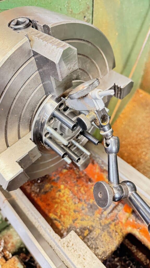
My 12” lathe is too small to place the hub in a four-jaw chuck with the posts and studs facing toward the chuck for the best way to re-machine the part. So I asked my friend, Al Lapp if I could come over to his place to use his larger 16” lathe. The way to fit a male and female taper is to chuck either in a four-jaw chuck (in our case, the main shaft) using a dial indicator, to center it. With the dial indicator mounted firmly to the lathe compound, I set its angle for 6° as a starting point. Then I placed the dial indicator tip on the shaft taper and run the compound with the dial indicator on it up and down the taper. Keeping the compound bolts snug but not very tight, tap the compound in either direction until the dial indicator needle doesn’t move from one end of the taper to the other. Tighten the compound nuts and re-check. Your lathe compound is now aligned perfectly with the taper on the shaft. Next, remove the main shaft, place the clutch hub in the 4-jaw chuck, center it in both directions with an indicator, and you are ready to fix the part using the compound only, indexed to the correct taper degree angle.
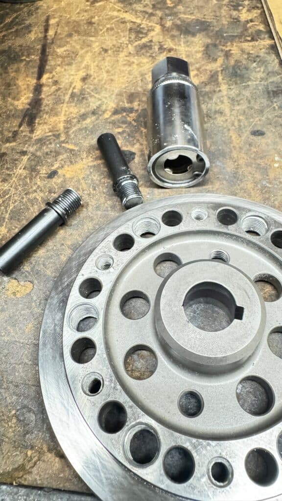
Unfortunately the hub wouldn’t quite fit his lathe either, placing it in the chuck with the large end of the taper facing out. So Al tried it with the small part of the taper facing out. The problem with this setup was, one couldn’t use the spare main shaft to check how far to cut without removing the hub, turning it around, bluing the shaft and checking it, then re-installing it, indicating and then take another small cut. If too much material were removed, the taper would let the clutch basket interfere with the case, ruining the hub. The only solution in my opinion was to remove the studs and posts so the hub could be placed in the chuck with the large end facing out, with the ability to check progress after every light cut with the sample main shaft. There was no obvious way to see how the black posts were held in place, installed or removed, so I wrote Bob Newby again and he wrote back with the name of a special tool stud roller remover that I would need to purchase, as well as how hot I would have to heat the hub (200° C, 392° F) to release the Loctite and unscrew the 10mm studs. This was very helpful on his part. The 6mm threaded studs came out by double nutting them and heat.
While at Al’s, we found that the taper in the hub is extremely hard and the tip of the tool kept breaking, most likely because of an interrupted cut from the keyway slot in the taper. The hub is also a bearing race so this accounts for its hardness. My solution was to use a die grinder, mounted to the angled compound set to correct indicated taper. It was a lot of work but absolutely necessary for this clutch to work well. Only a small amount had to be ground off, just enough to change the taper to the correct angle. Interestingly, Eric spoke to several people he knew on Facebook with Newby Clutches, and they all take similar steps to make the part work correctly on Triumph’s and BSA’s. As I said before in post #1, “100 years of tradition uninterrupted by technology” is what was often said about the British bike (and automotive) industry. I suspect this holds true for Bob Newby although this part is otherwise beautiful.
Since the hub without the studs installed would fit my 4-jaw chuck, I repeated the indicating process on my lathe and set my compound. My brain must have been on autopilot because I didn’t realize until too late that reversing the hub in the chuck would give me a mirror set up when I cut into it. In a knucklehead move, I cut into the hub, ruining it. Not my best day.
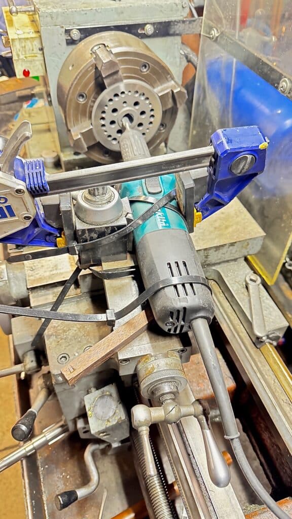
I emailed Bob Newby, purchased a replacement hub, which arrived 2-1/2 weeks later. As I suspected, it had the same fit issues as the hub I destroyed. I set up the hub in the lathe using the previous steps, except this time indicating the compound on the lathe to roughly 6° on the other side of the zero mark. BTW, when I indicated the taper on the BSA main shaft, the hash lines on my dial read about 6-1/2°. I don’t know if my dial is correct or not, but either way Bob Newby’s taper is not identical to the main shaft it is supposed to fit. Then, since I knew that the cutting insert in a boring bar would chip because of an interrupted cut from the keyway slot once again, I rigged up my electric die grinder, attaching it to the compound. My attachment method won’t be seen in any machinist magazines, but using several large zip ties, a bar clamp, and a tapered piece of wood for the height adjustment, I made a usable setup. One thousand and one uses for zip ties, now one thousand and two.
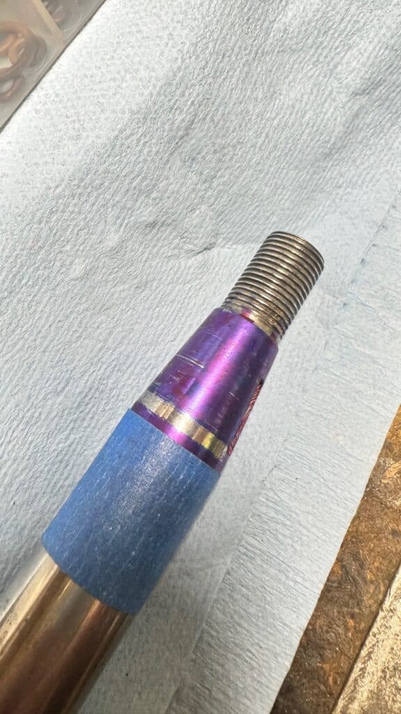
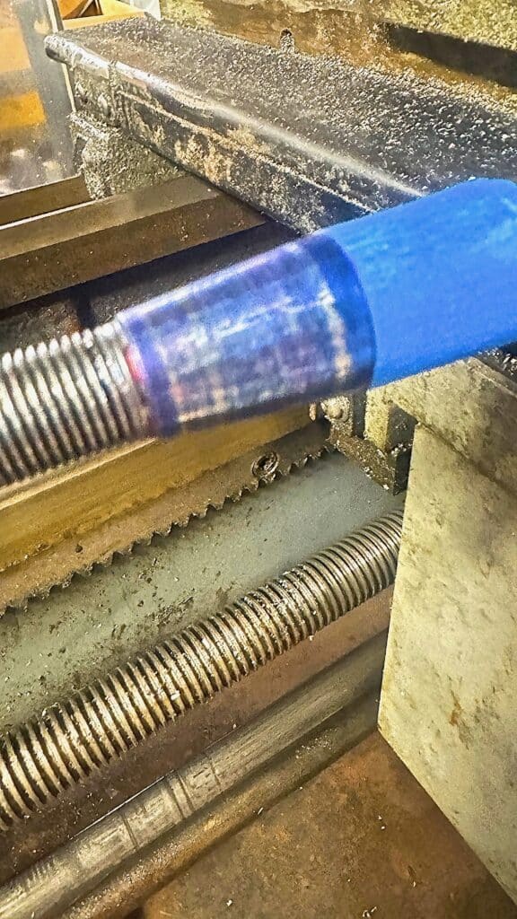
The end result solved the clutch hub issues, both the taper fit and the belt alignment. I cut the taper with a carbide cylindrical burr in the die grinder, checking the fit often until the hub went to the stop mark I taped onto the test shaft, and the taper scraped the blue dye its entire length. Now with the correct taper, the 2 parts stick together, like they should, for a good interference fit. A lot of work and one ruined hub to get what I should have gotten with the hub in the first place.
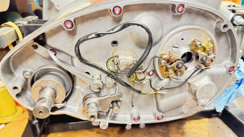
We are getting close to placing the motor into the frame. What’s left before installing in the frame is setting up the alternator, phasing it with the rotor for maximum spark timed with the points opening, timing the motor, and making new pushrods. Either the new cylinders or the high lift cam or both require custom pushrod lengths. To be continued!
Larry, thank you for continuing to send me updates on the BSA build. I read, and re-read with rapt attention to every detail in your well-written, clearly descriptive words and photos. The fin on the cylinder looks exactly like the other fins except for the tiny mold parting line on the original fins! I was quite surprised that the custom clutch manufacturer was unwilling to admit to the improper taper on the clutch hub. I was very amused at your attachment of the die-grinder to the compound, I’ve utilized the same method (including the zip ties) for the same procedure in cutting hardened components on my South Bend 9-inch lathe. Please keep me “in the loop” for further updates, I truly appreciate your “constant diligent attention to detail is the price to be paid in the pursuit of excellence”. I stole that line from a car restoration magazine and kept it as the slogan of my own business, remember: “All work and no plagiarism makes for a dull story”! David Riddle