June 3, 2023
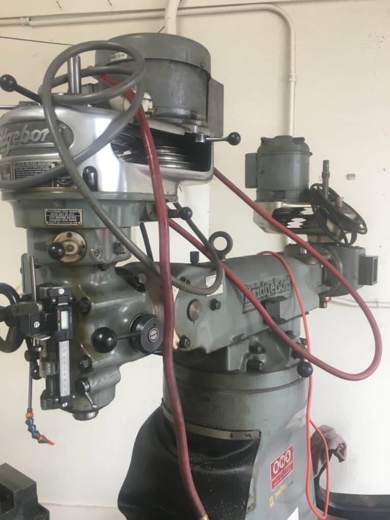
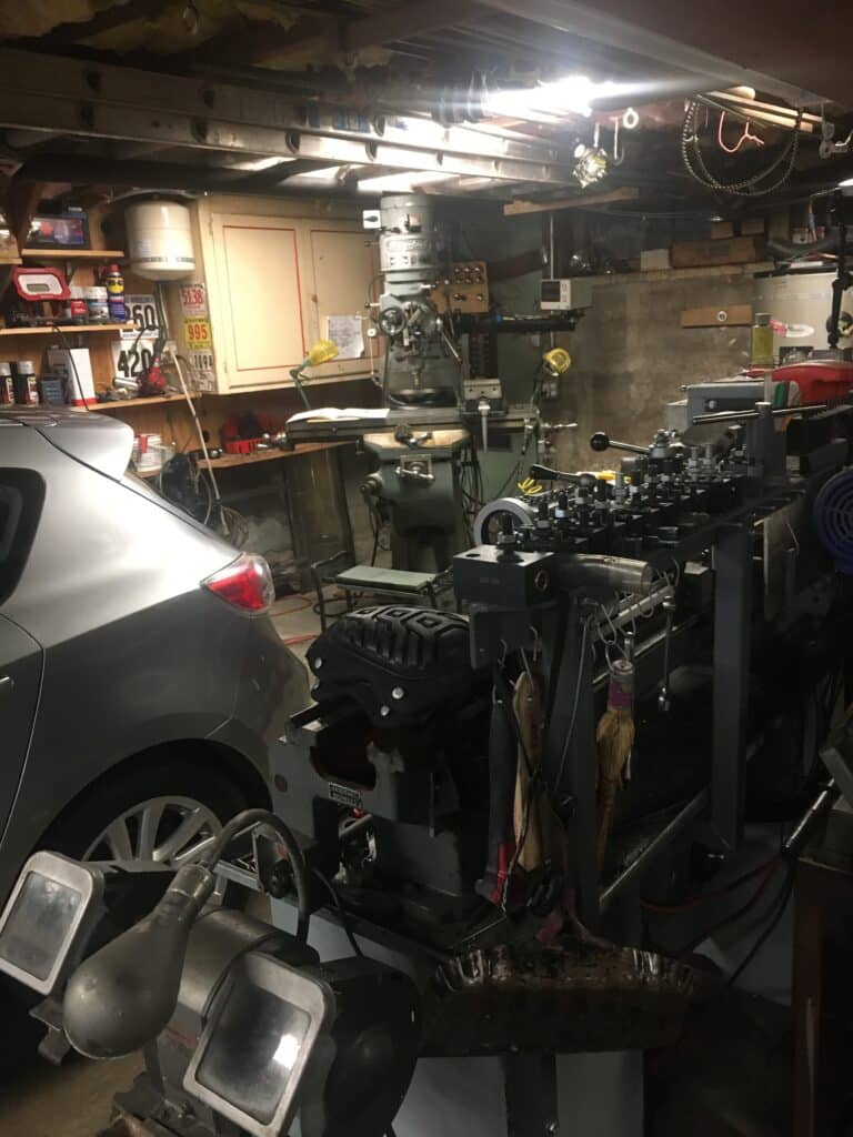
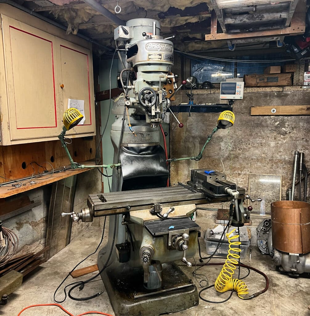
Before I get into this report, the big news for us it that we now have a Bridgeport vertical mill in my shop. Eric found a 1974 J-Head model in pristine condition from a shop in Berkeley, about ten miles away from San Francisco. A J-Head model clears my low ceiling garage by a couple of inches. It’s also 240-volt single phase, which allows me to wire it directly into house current without a phase converter. We purchased it from a man who is retiring, Laurence Anderson, who used it in restoring high-end cars. The mill came with a lot of tooling such as a mill vise, a digital readout (DRO), several boring heads, chucks, collects, fly cutters, etc., and has power feed on the X and Z axis. It also has a Cherrying head that can be used for making convex and concave shapes. CNC machines that have 3, 4, and 5 axes have mostly replaced Cherrying heads and we most likely will try and sell this separate head, as we don’t see much use for it in our operations.
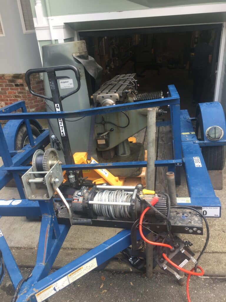
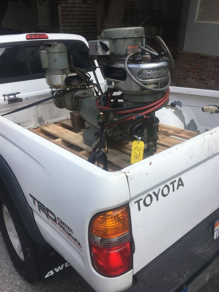
Getting this machine into my garage was a BIG deal and it had moments of angst and excitement! Eric rented a drop-bed trailer and a pallet jack. He brought over his engine hoist and a 12-volt electric winch. We removed the heads and ram and placed them as a unit onto a pallet in the back of his truck, using the forklift at the shop in Berkeley. The base and mill table, already on a pallet, were lifted onto the trailer and everything was strapped down tightly. The trip across the Bay was uneventful and the fun didn’t start until we backed the trailer as far as it would go into my down slope driveway. I live on a fairly narrow one-way street, which had anxious cars lined up until we could block the wheels and disconnect the trailer from his truck.

Because of my disability, I was less help than I would have liked to have been, and Eric worked his butt off. My wife Nancy came out to help us too, and we lowered the trailer floor, clamped the winch to the trailer frame and wrapped the winch cable around the mill base. With pry bars we started moving the mill, strapped to a pallet jack, down the trailer bed using the winch for a brake. This thing is very heavy. It’s like moving a 1958 Buick without wheels! Unfortunately, the uneven slope of my driveway kept the last four inches of the trailer bed off the ground. We very slowly, easing out the cable with the winch, lowered the base off this 4-inch “cliff” onto the lower part of the driveway and using bars and a pallet jack moved it on to the garage floor.
At this point, luckily, a couple of Eric’s friends came by and helped us use the cherry picker engine hoist to remove the ram and both heads from the back of his truck and the four of us guided the hoist down the driveway and into the garage floor. The next day we used the bars and a pallet jack to move the mill roughly where we wanted to place it. Next we hoisted the ram and heads onto the base, lifted everything off the pallet jack with the engine hoist. We used the come-along and bars to slide it to its final (I hope) spot in the shop. A couple of days later we ran 240-volt and 120-volt circuits behind the mill and were in business. The mill will be put to use shortly when we convert the bushed timing side engine bearing to a roller bearing, and for many other projects.
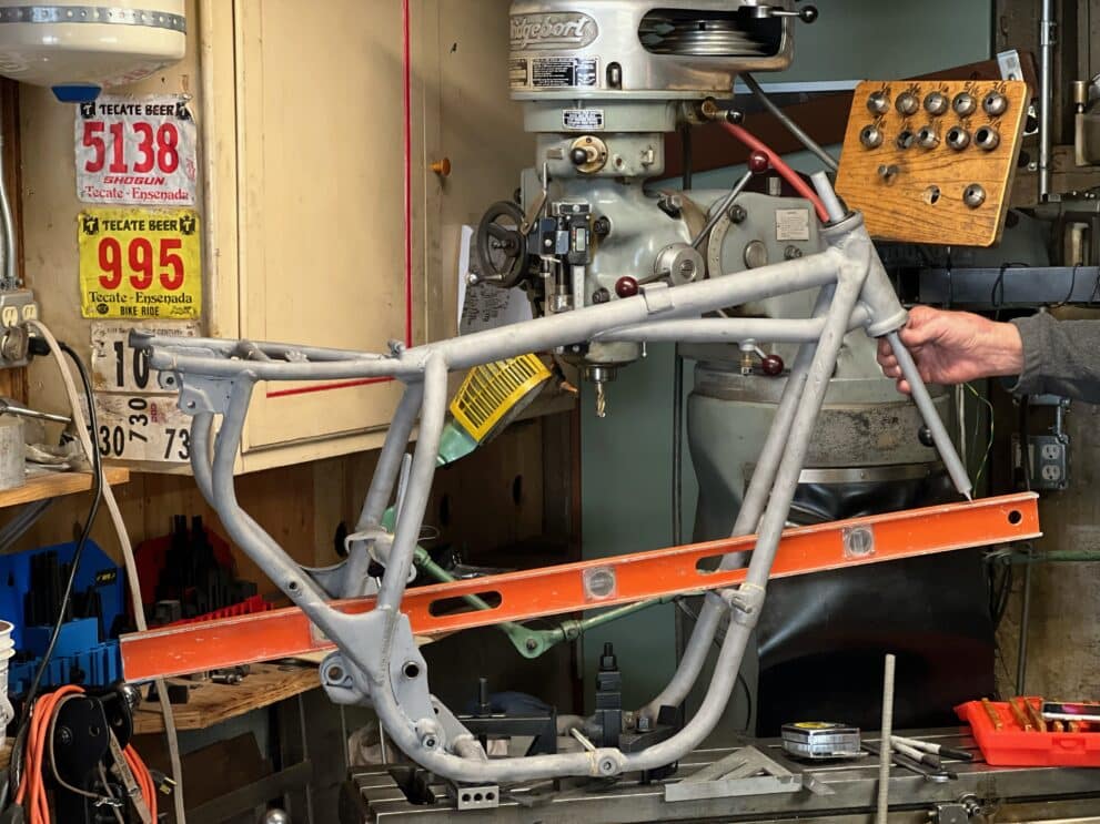
Meanwhile, work on the BSA continues. Our plan is to get a roiling chassis completed before starting on the motor. As I had mentioned in a previous post, this bike had been trashed hard by the previous owner in 1964, before I owned it. I was new to motorcycles when I purchased the “basket case” and just put it together and rode it, doing needed repairs or improvements as they came along and learning along the way. Inspecting the bike now reveals many issues and quirks that we will address before paint or powder coating and assembly. To my eye, the most noticeable issue was the 1/16” or less clearance between the lower rear of the primary case and the frame. Quite honestly, I never saw this until Eric and I started in on our overhaul and even then we had to check out another A-65 BSA to confirm the close proximity from the primary case to the frame
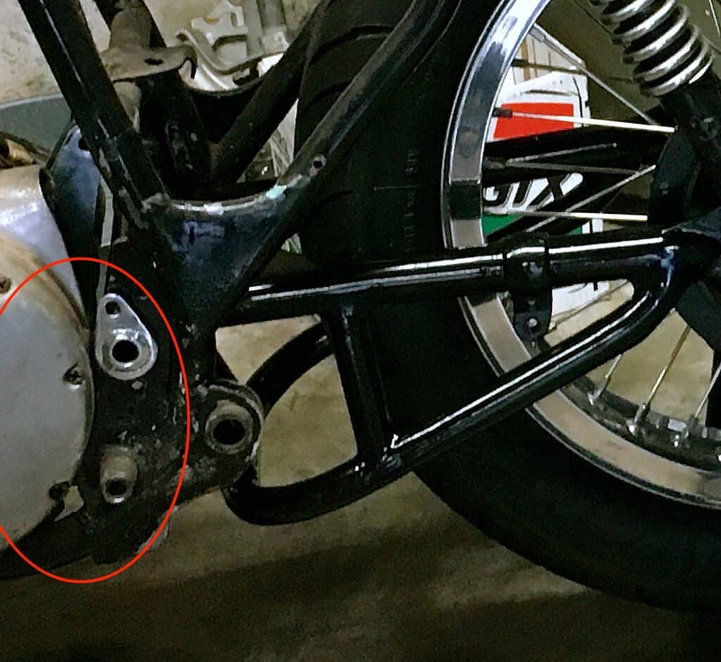
I knew there was some welding performed before my ownership and I assumed it was OK. Never assume! After removing the motor and the frame was bare, we started checking everything out. It became obvious that a section of the frame had been replaced by the previous owner, most likely in a crash. I knew this when I first put the bike together and thought it was done correctly, aside from the three not very clean welds that looked like they were made by an inexperienced welder using stick welding. I had made a pair of gussets when I first got the bike and welded them on for peace of mind because of the sloppy welds. We then started taking carful measurements on the right side of the frame and comparing them to the left side. Using the front engine bolt and the swing arm axle measurement, we measured a 3/16” shorter measurement on the left side of the frame. Bingo. This is why the frame is so close to the engine case.
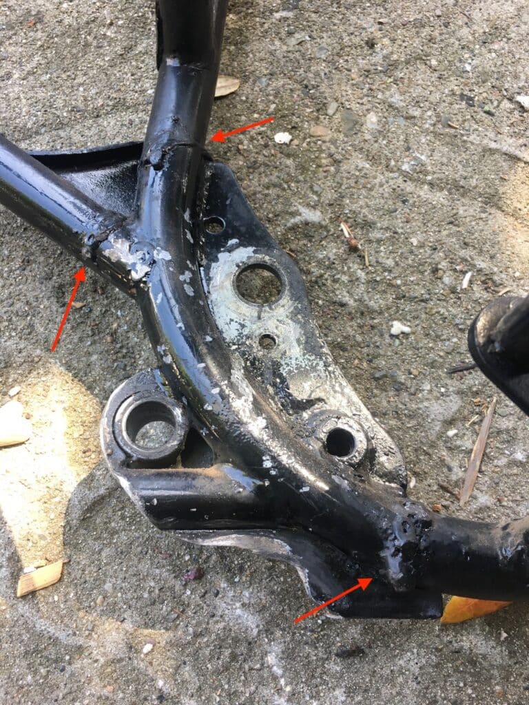
I consulted by phone and email with my friend, Al Lapp, about my plans for frame repairs, and dove into the project. After having the frame sandblasted, the fix was accomplished by turning a spacer to the needed size to correct the measurement, including the kerf, to the frame cut and TIG welding it in place. Doing this allowed us not only to get the same front to back measurement on both sides, but it also allowed us to cut the frame for this spacer where the old ugly and probably weak weld was located.
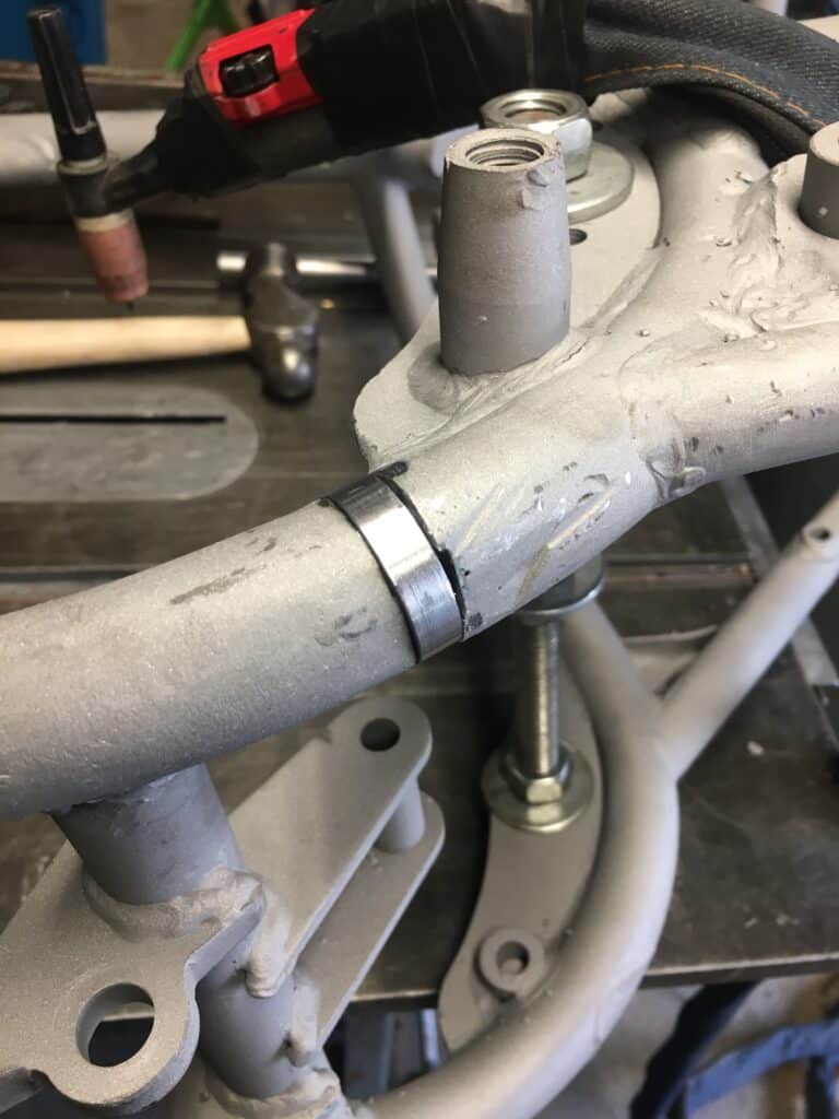
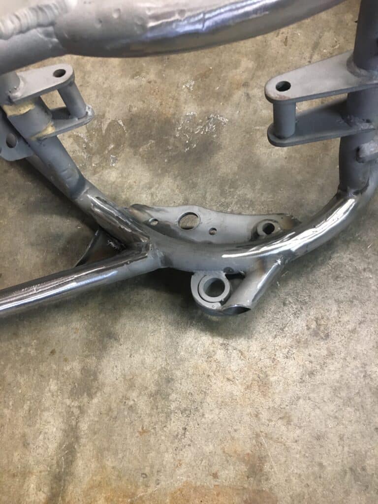
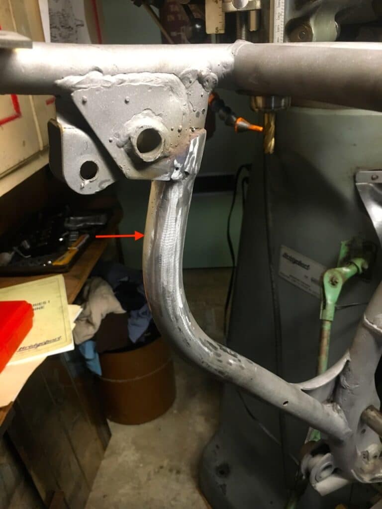
Since the part of the frame that was replaced was connected to three tubes in total, we wanted to check the other more vertical measurements from right side to left side. Using the measurement from the original right side as the correct measurement, we checked the main frame tube (the forward tube) on the left side against it. That welded member was spot on with the right side. All we had to do here is go over the crude weld to be sure there was good penetration. Now that two tubes were correct and welded properly, we measured the right and left side of the third tube, which interests where the shock mounts to the seat tube. This tube was welded a strong 3/16” longer on the left side. The extra tube length caused the left rear shock to mount 3/16” higher, and also twisted the seat frame to hold the seat that much higher on the left side. This tube was the least important of the three, but also fairly easy to fix, by simply cutting 3/16” section out of the vertical part of the tube, compressing the cut and welding. I re-welded the other two sloppy welds, for peace of mind and also aesthetic reasons. Last, a quick install of the motor and bolts to make sure everything still worked with the equal right and left measurements.
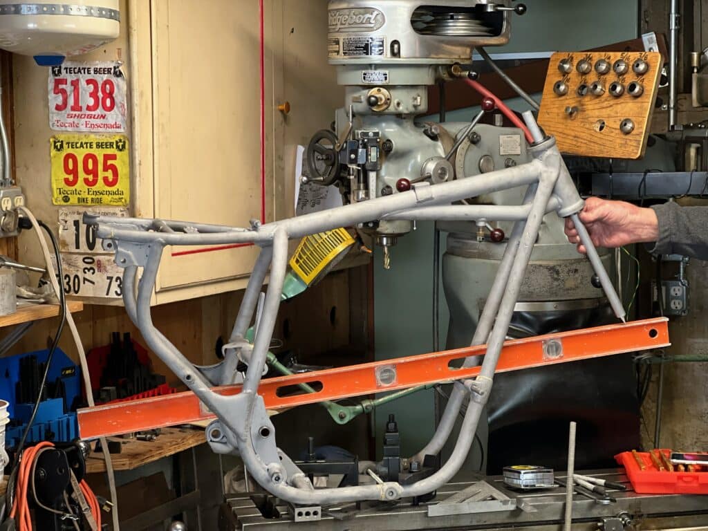
The next step was to check that the frame alignment was straight. We did this by clamping the frame to the mill table with the swing arm axle and the front engine bolt both parallel to the table. After careful measuring and clamping tightly to the table, we then measured the centerline of the swing arm axle and the front engine bolt and marked them. Then, we took some Delrin round stock and cut tapers on the end to come close to the taper of the Timken bearing races pressed into the head tube of the frame. I bored a ¾” hole in this for a piece of ¾” aluminum that I turned to a sharp point on one end. Using the Delrin “plugs” to hold the aluminum, we adjusted it until the point just touched our straight edge that was clamped to the centerline marks on the axle and engine bolt. Any adjustment in the head tube alignment was done with a 3-foot construction wrecking bar, placed in the head tube, tweaking it until the point of the aluminum rod was in the correct spot. Once done, I carefully welded the head tube gussets to the frame, going back and forth from side to side to minimize warp movement. When complete, frame alignment was checked again and was right on.
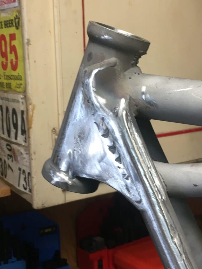
We still have to weld on some gussets to strengthen the swing arm mounts, more frame cleanup to do, and a lot of trial fitting, but I’ll cover this in my next post.

Larry and Eric, this is an amazing blog. Fascinating restorative work. Jeeez just the pick up and delivery, offloading of the mill into your driveway and garage had me sweating billets / bullets.!
Loving the posts.
Hi Keven, Thanks for the comments. The Rickman Triumph was published in an article here: https://www.returnofthecaferacers.com/triumph-cafe-racer/kosman-rickman-t120/
We are almost finished with the chassis on the BSA Hornet and a new post, #4, will be coming out in a day or two. Moving the mill was exciting in the scariest sense. We almost lost it at one point, saved by the jamb on my garage door! That sucker is HEAVY!!