August 4, 2023
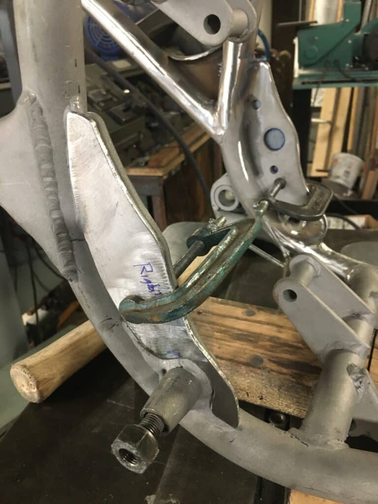
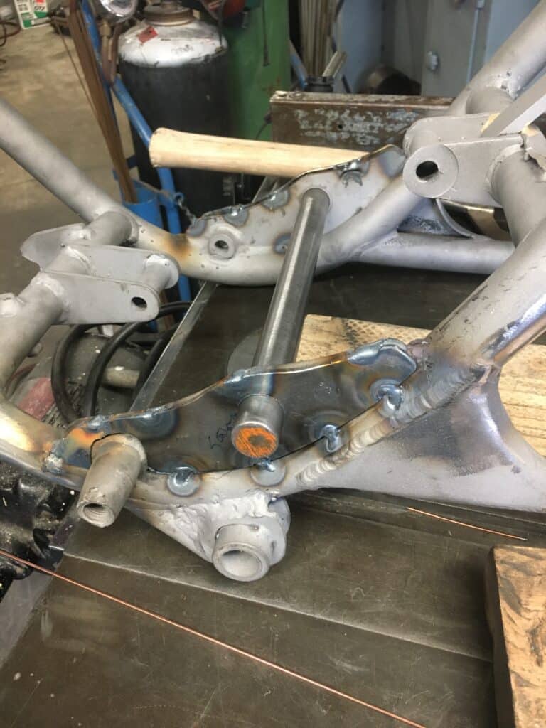
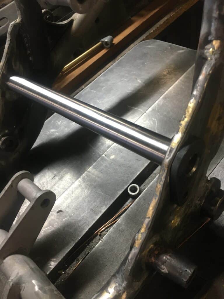
After our preliminary frame alignment, I cut out a pair of steel plates matching the plates already on the frame, which support the swing arm axle. I wanted to double the thickness of these plates in order to stiffen the frame where the swing arm axle goes through it. BSA’s frames are a combination of welds and brazing and since the two don’t mix, if there is any brass where I would have liked to weld, welding is out unless 100% of the brass can be ground off. By clamping the new plates over the frame plates, I laid out where the hole for the swing arm axle goes and drilled it to the original axle size of 13/16”. Using the axle and clamps to align the old and new plates, I TIG tacked each side in 7 or 8 places and then brazed everything together. Once this was complete, we line-reamed the frame axle size out to 7/8” for my new 7/8”, 4130 chrome molly axle, which I machined from solid stock and then threaded on my lathe. We drilled out this bar stock to make it a hollow axle and I welded a tab that I cut out on the opposite end of the threads in order to bolt the axle to the frame and keep it from rotating. We now have a larger diameter, stronger swing arm axle along with a stiffer frame in that area.
We were about to check the frame alignment one last time and decided to really go over the frame first to check for any bad welds or any other issues. We found a big one! After cleaning up the head tube area when I welded on the head tube gussets, we discovered several cracks next to factory welds in this area. I suspect this was caused by improper factory welding and or cooling after welding. It’s only because I sandblasted the frame that these cracks showed up at all. All of them are recessed around the head tube and the black paint and shadows hid them well. This is a critical area of the bike for safety and also for frame alignment. Although I am improving all the time, I still don’t consider myself a great TIG welder, so I decided to have these cracks welded by someone with a lot more experience. I have confidence in my welds for penetration, but I think I tend to overheat the metal. I wanted to be sure this didn’t happen since heat causes all sorts of movement in metal and we had just aligned the frame. Also, a couple of the cracks were deep up where the tubes come together, a little hidden behind our new gussets, and I knew I would feel better if a more experienced welder did this work.
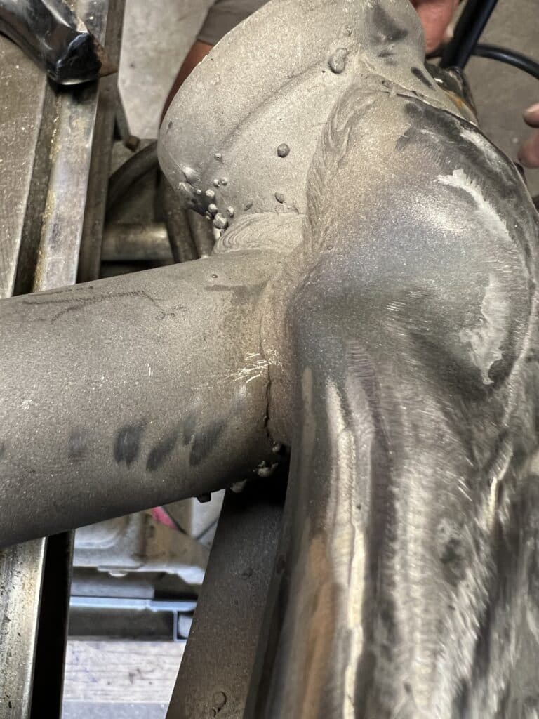
Eric called a man he knows in Rodeo, California, Shawn Campbell, who said he could weld the frame. Shawn does vapor blasting too, and he had already vapor blasted the front brake drum earlier in the build. When he saw the cracks, he told us that this was not uncommon on non-lugged British frames. We left the frame, found a coffee shop and came back a little while later. The repair was beautiful, which made my decision to sub this out even better! Since the cracks were on both sides of the head tube in four different places, Shawn welded small sections from one side, then the other side and back again, hoping to maintain the alignment. When I got back to my shop and set it up again for the final alignment check, everything was spot on.
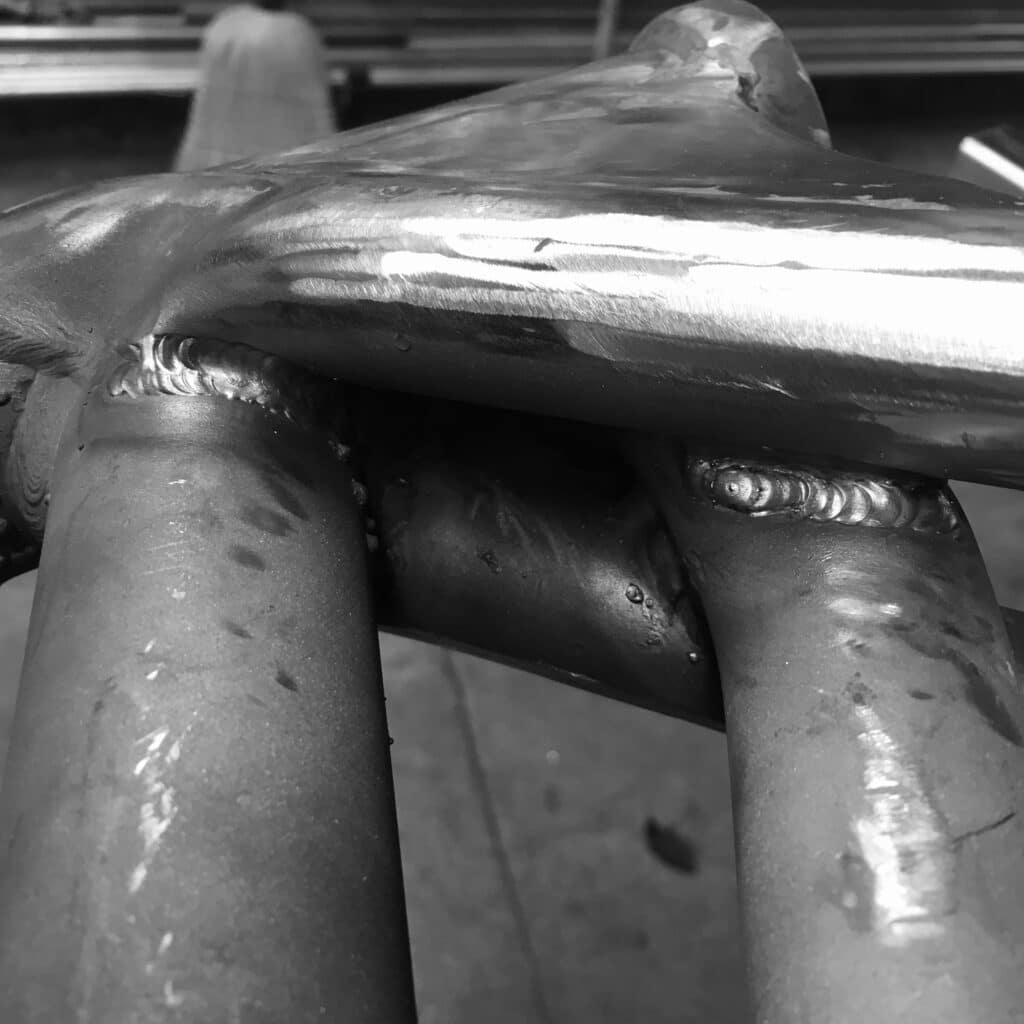
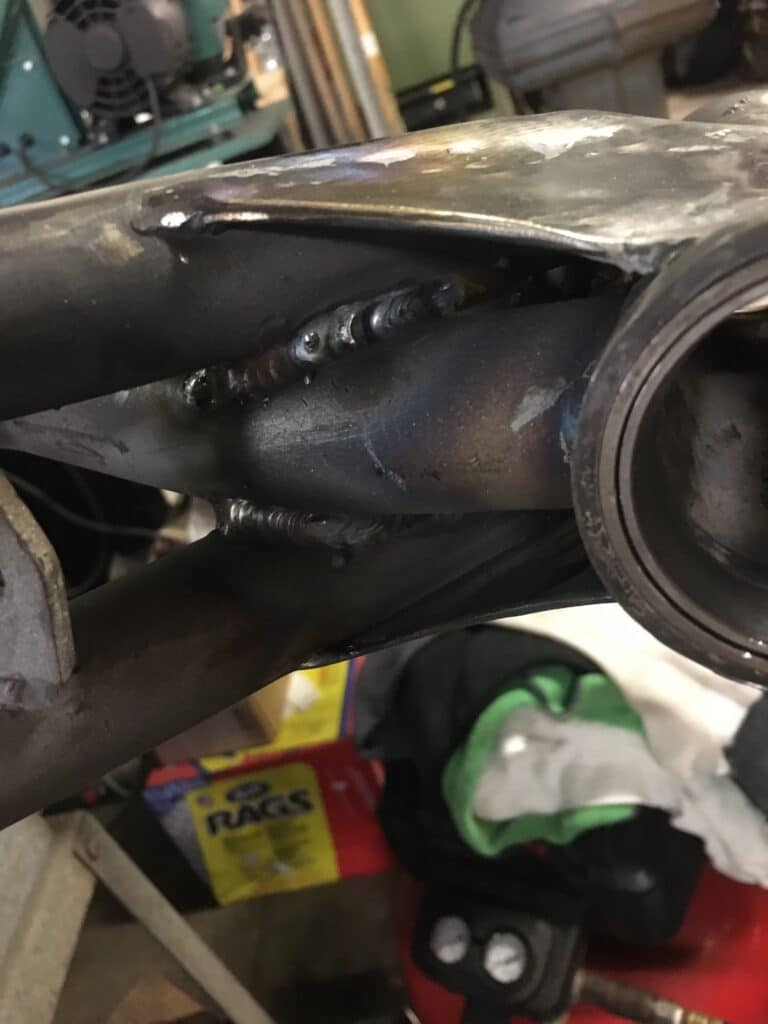
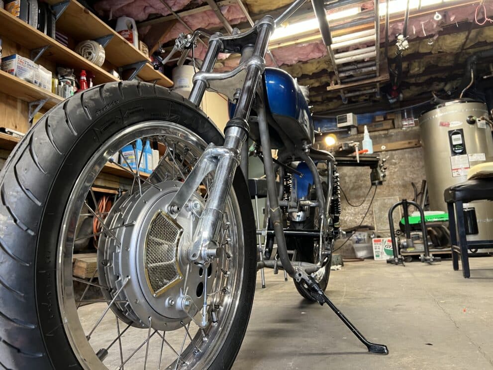
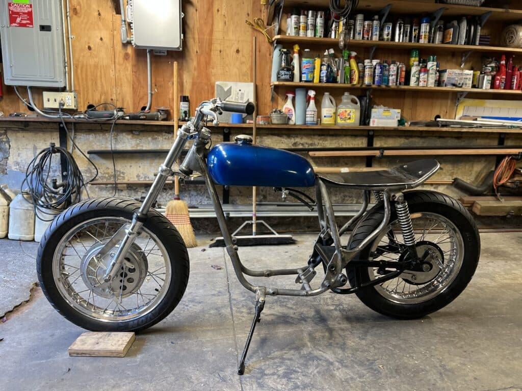
Now it was time to start trial assembling the frame. I found a kickstand and spring and installed them. We mounted the front end with the wheel in place, and then the swing arm and rear wheel. Eric brought over some handlebars he had, and we had a rolling chassis. We needed to start dealing with the seat and fender. I purchased a stainless steel, 4” generic un-drilled front fender, to use on the rear wheel. Our first thought was to purchase a generic seat from somewhere, but this proved to be incredibly difficult. I ordered one which was junk and sent it right back. We looked at dozens, and none seemed quite to our liking. Finally we decided to make our own seat pan and have it upholstered. This way we could get the shape we wanted and also the size we wanted. We quickly discovered that the seat, the fender, and the rear fender support are all related to each other. This bike’s frame had been cut off by the previous owner just behind the rear shock mounts, so there was no rear support for the rear of the fender. I decided that a rear loop should be fabricated which not only could support the rear of the fender, but also support and shape the rear of the seat. There are many rear loops sold online, but I couldn’t find a 10” centerline one. They seem to all be around 9”, perfect for many Japanese bikes.
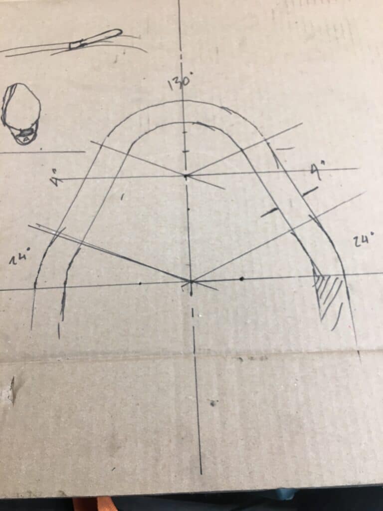
Not having a tube bender, I asked my friend Al Lapp if he could bend a loop for me on his bender out of 1” tube. He said to come on over and we could bend something. Since my frame required a centerline diameter of 10”, and Al only had a 6” diameter die for 1” tubing, he came up with a part that was absolutely perfect. He drew up on a piece of cardboard, a full scale drawing that had a 6” diameter bend that tapered then bent into the rear of the frame. The finished part had a teardrop look to it and it really sets off the bike. The seat pan will be cut to this shape, too. I took the loop back to my shop, cut off the excess legs, and machined a pair of lugs that I could weld into the loop and also fit the frame. It took a little tweaking to get everything looking right and centered, but it finally came together.
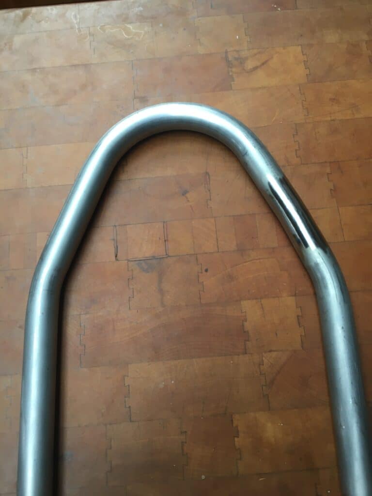
Next, we wanted to mount the fender. The flat rear loop was too low. I knew we would have to raise the back end of it in order for the fender, which would mount to it, to have enough clearance for the full 3″ shock travel and then some. Using a thin cutoff wheel, we cut almost through the rear loop on either side and started bending it upwards while checking the fender clearance. After 5 or 6 cuts, we got the height and clearance we needed and I welded the loop back together.
Then we made some tabs that I welded on to the outside of the seat loop to bolt the fender to it. This proved to be a slow process and a balancing act, trying to hold everything in place and in line. The tabs had to be just wide enough for the taillight bracket to fit between and not too wide for the fairly narrow fender. In the end, it all worked out well. I welded on another pair of tabs for the seat pan to be held down with bolts. These were a little easier since all I had to worry about was having at least 4” of clearance between the tabs for the fender. Last, I drilled 4 small holes, 2 on each side, which I drilled and tapped in order to bolt on the tailpiece. I could have welded the tailpiece to the frame permanently, but with all the trial and error fitting and my lack of mobility, it was much easier to build what I needed with many trial fits, and then bolt everything together. Also there was brass in this area from factory tabs so welding was out. When bolted together, everything is solid and strong and the addition of a bolted-down seat pan attached to the rear loop will add to that strength.

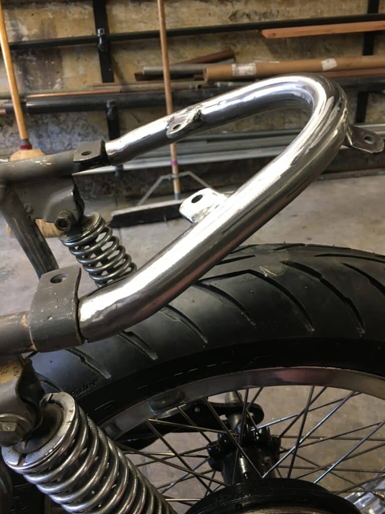
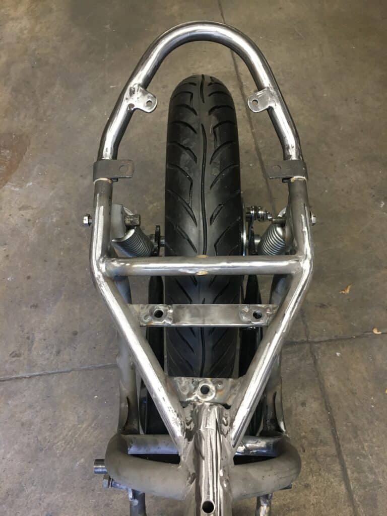
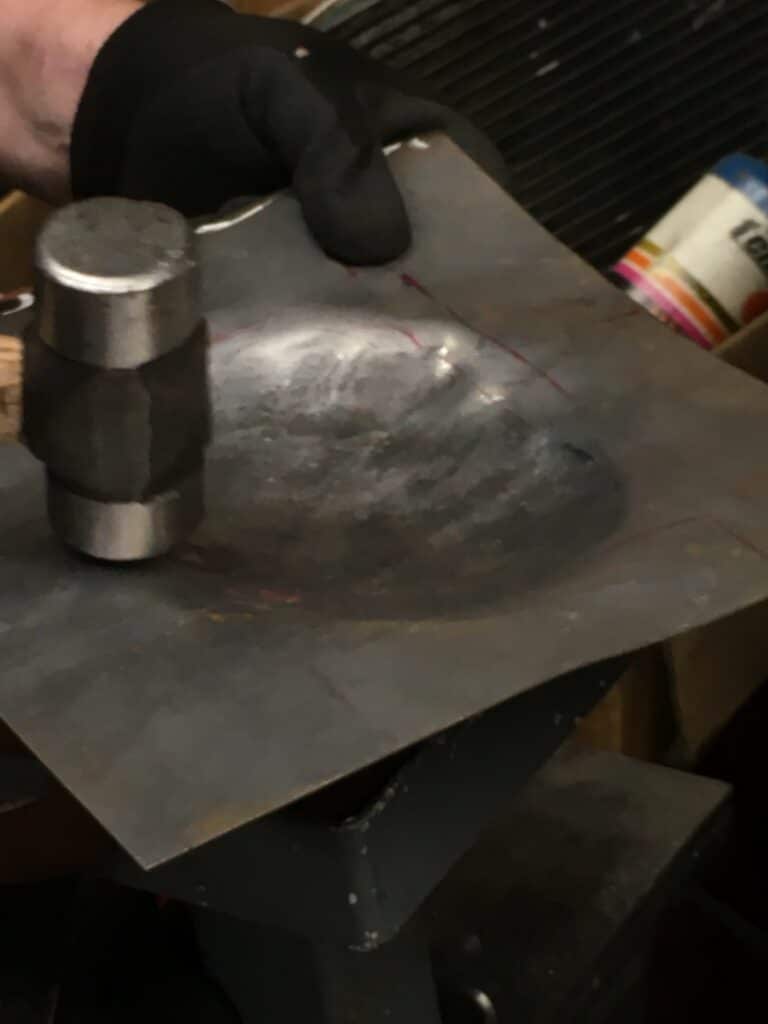
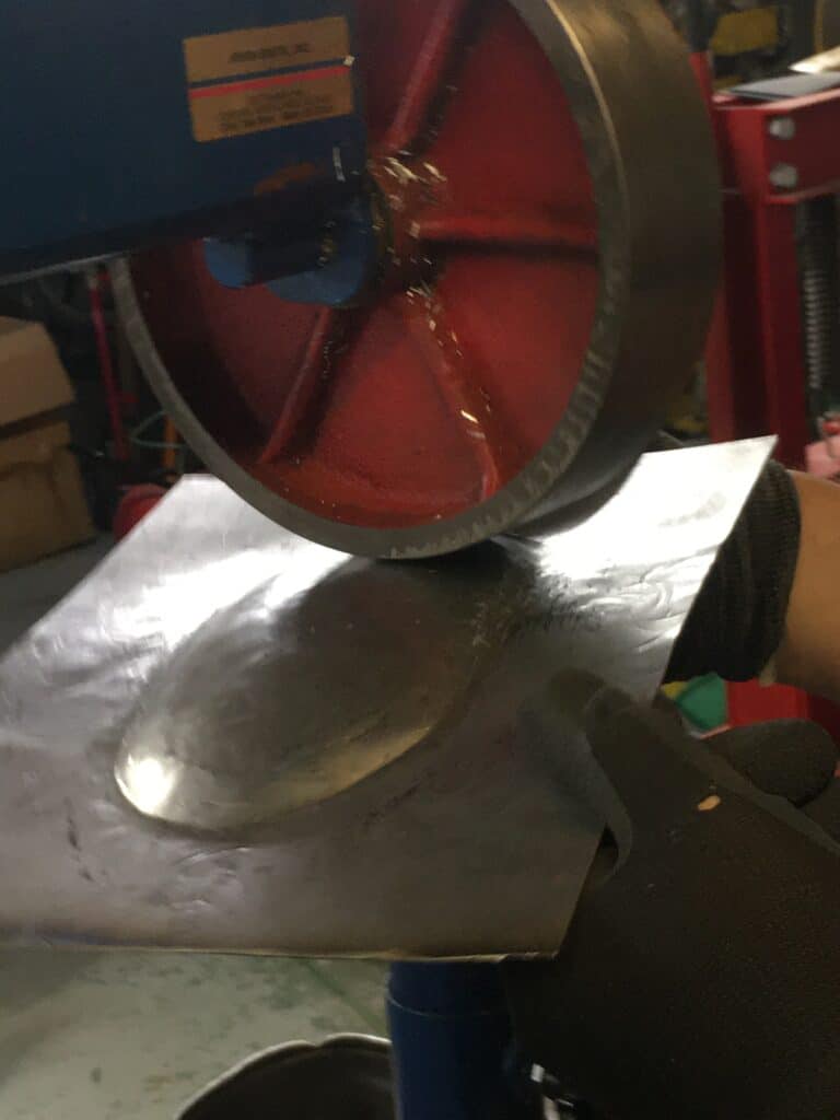
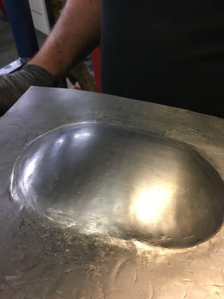
It was time to make a cardboard pattern for the seat pan but another issue arose which I didn’t expect. The fender, when mounted to the rear loop, now stuck up into the rear part of the seat pan! I took a look at the stock BSA seat I had and sure enough, there is a depression extruded into the metal pan for fender clearance. To accommodate the clearance I needed, I decided to cut an oval out of the new pan for fender clearance. I was going to weld segmented strips of 18-gauge sheet metal over the fender to cover it, but my friend Al Lapp informed me that he had an English wheel. He said we could hammer a one-piece cover, roll it smooth, with the English wheel, and weld it to the seat pan. Like everything else, it turned out to be slightly more complicated, since the bend in the seat pan fell in the middle of the “hump” placement so a small seam was then cut and re-welded in order for the “hump” to sit flat on either side of the seat pan bend. Al did a fantastic job on the pan “hump” and the sad part is that it won’t be able to be seen or appreciated in person by anyone else but me, Eric or Al. The entire seat pan will be covered in foam and upholstery! It most likely won’t even be felt when sitting on the seat, as most of the fender cutout “hump” is at the rear of the pan anyway and is only ¾” at its highest point, tapering to nothing at either end.
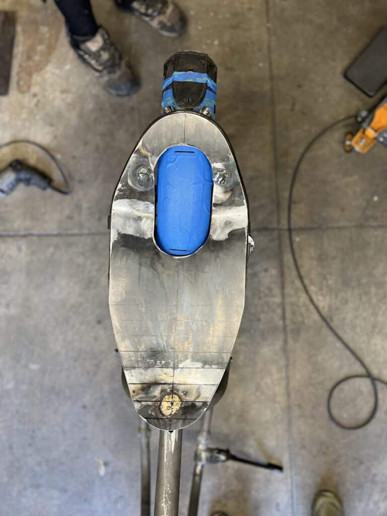

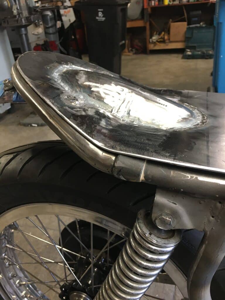
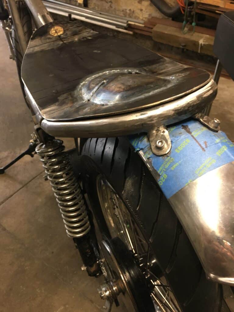
Then I cut off the stock front seat mount, which allowed me to set the front of the new seat pan about ½” lower on the frame. I drilled a hole in the frame and sleeved it for the front seat pan bolt. The finished and painted seat pan will now be sent off to Portland, OR to be upholstered by New Church Moto sometime next week.
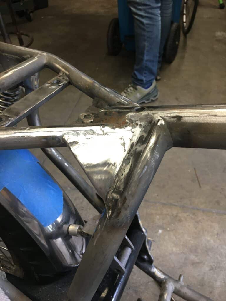
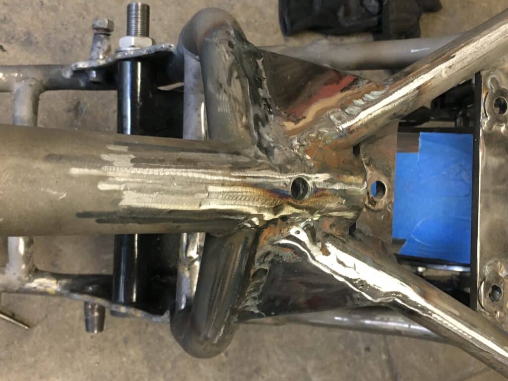
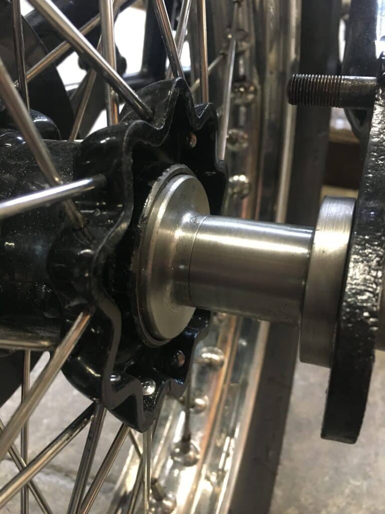
We also decided to add a pair of small triangular gussets to the frame where the main rear frame tubes intersect with the rear end of the top tube. The frame is stiffened here now for the upcoming much more powerful engine and this should help handling as a bonus. Along these lines, I also made an axle spacer with a thick, larger flange for the rear wheel that really supports the swing arm flange on the right side, to stiffen the rear dropout.
Some minor frame checks, a trial fit of the engine after all the welding, and then the frame goes off to painting or powder coating. The take-a-way from all this work is something I still haven’t learned in over 60 years of projects and construction. Almost everything is more complicated once one gets into it and nothing usually goes as easily as we suspect it will. There are no 10-minute jobs!!!

Comments