April 15, 2024
This post Is technical in nature and may not interest all the readers on my email list. It is a detailed record of our modifying my 1964 BSA Hornet engine from a bushing to a roller bearing on the timing side (TS). It also is about “blueprinting” the engine at the same time. It’s long and detailed and will be in at least 2 parts.
To install a roller bearing in an A50, A65 or A70 BSA, the flow pathway of the oil to the crankshaft must be changed. As it came from the factory, oil was pumped from the oil pump, through a passageway cast into the cases, which flows to the timing side (TS) crankshaft bushing. That same passage was split and also went to the pressure release valve (to keep the oil pressure constant and not too high), as well as to an oil sender unit for a warning light or gauge on later models. From the timing side bushing, the oil continues on through holes drilled in the crankshaft, through the sludge trap (a centrifical “filter” of sorts inside the crankshaft), and on into the connecting rod bearings, all under pressure from the oil pump.
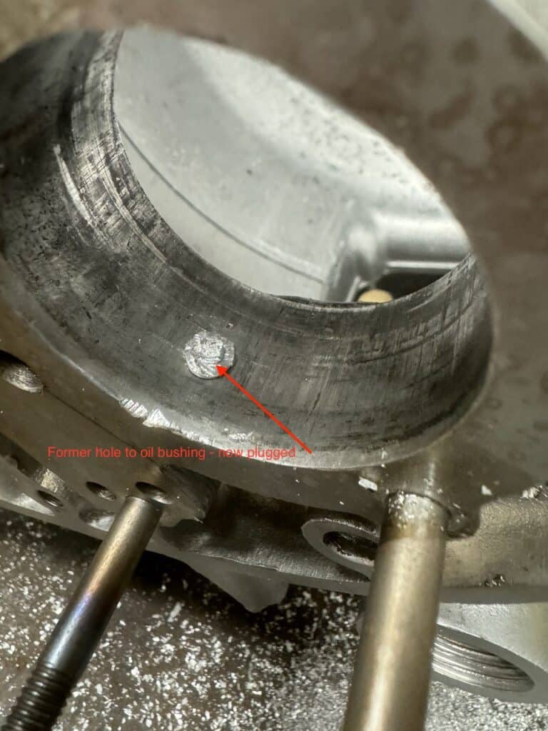
To install a roller bearing, the feed to the TS bushing must be blocked off and the crankshaft must be modified for end feed oiling. Otherwise oil going to a roller bearing through this galley would lose most or all of its pressure slipping through the rollers, and the rods would not be fed oil because of this loss of pressure at the new roller bearing. Bushing type bearings require a thin film of engine oil under pressure to keep the rotating metal on metal from actually touching each other. In fact most of the wear to this type of bearing comes from dirt and grit in the oil, or, overheating and oil breakdown. With this roller bearing conversion, the crankshaft is modified by drilling a hole in the end of the crank on the TS. Oil from the oil pump is then re-routed into the end of the drilled and modified crankshaft, which travels on through the sludge trap to the connecting rods. We blocked off the oil passageway to the bushing by turning a slightly tapered plug to drive into the oil hole in the case to seal it off. The plug can’t be too long, otherwise it will block the oil flow elsewhere. The new outer roller bearing race, pressed into the case, will keep the plug in place.
Over the years that the A50, A65 & A70 were made, there were several changes to the crankshaft and cases. Because of these changes, your installation may vary slightly. Further I have seen a couple of ways of making the changes needed for a TS roller conversion. None that we have seen are “wrong.” After looking at what information we could find, we decided on the path we are taking. It’s not the only way, but we feel that this is a robust way that should work well and be easy for a rebuild in the future. Once complete, it will only take an o-ring and an oil seal, in addition to stock gaskets, for a rebuild. Some people have modified the oil pump itself in order to make this modification, but we rejected this method. At $400 for a new Hepolite or SRM pump, we didn’t like the prospect of possibly screwing one up. Besides, our pump will be replaceable in the future right out of the box. If you attempt this modification, check out some of the other ways. The last year or two before BSA went under, they had cases that make this modification look even easier, and I think they were headed in the direction of roller bearings on both sides of the engine. But whatever year of your motor, the end result is to get the flow of oil into the end of the crankshaft on the TS while maintaining oil pressure to the connecting rods.
To my knowledge, I think the early version of the engine had a slightly narrower crankshaft that used a ball bearing on the drive side (DS). Early motors didn’t have a casting for an oil pressure sender for an “idiot light” and also didn’t have a notch in the crank and corresponding fitting in the cases to locate top dead center. Later cases added these features. However, with some minor work, a later crank with a roller bearing on the DS could be fitted into early cases. I did this years ago, when I replaced the crankshaft after breaking it. I can’t remember exactly what else was needed to accomplish this, but it was minor, most likely different shims to get the proper side-to-side end clearances. I don’t remember if the roller bearing had the same outside diameter as the ball bearing, but I suspect it did.
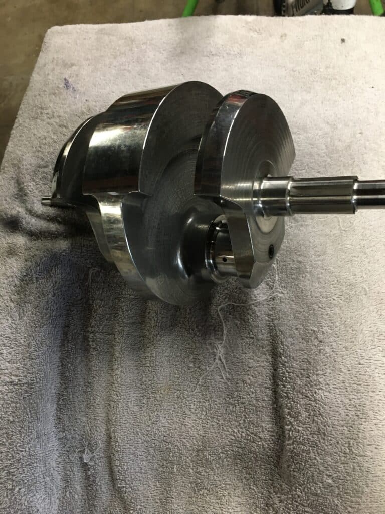
In our case, we will not have to modify the existing crankshaft TS end for a roller bearing as we have obtained a new crankshaft made from a solid billet round stock steel, 4340 grade, that is already drilled and machined for the TS oil feed and rotary seal. It also has a longer throw (a stroked crank), the same stroke as the latest BSA A70’s. Since there were only 200 A70’s produced in the last year before BSA went under, those crankshafts are very rare. We were very lucky to get this crank from the machinist who built it, Greg from Ro-Dy Crankshafts in Plymouth Michigan, as he was retiring and is no lnger in business. Because of this, we got it at a good price. It is far stronger than any crank BSA ever made and can safely rev much higher. Further, our new crankshaft does not have a sludge trap either. In my opinion, the sludge trap is not needed if there is a good oil filter and the oil and filter are both changed at regular intervals. British bikes did not have any filtration, short of a screen to keep the largest particles out of the engine. Only the British could design an engine that one would have to tear down to the very last nut and bolt, just to clean this crude sludge trap “filter”, rather than incorporate a replaceable external filter. I recommend you throughly clean your sludge trap EVERY time you do a complete teardown on any British bike, AND install a spin on oil filter into the return line to the oil reservoir.
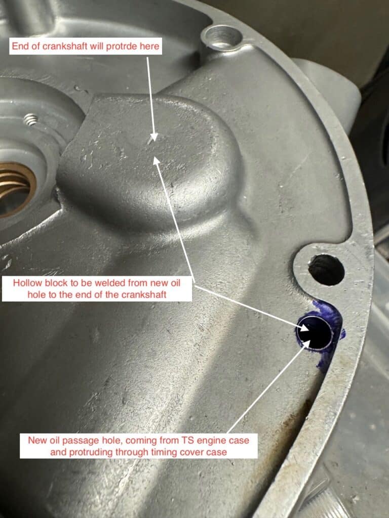
Ultimately, the crankshaft has to protrude through the timing cover case for the newly routed oil flow to enter it. Stock cranks must be modified by extending them with a turned extension to accomodate an oil seal. Our new crank is already set up this way.
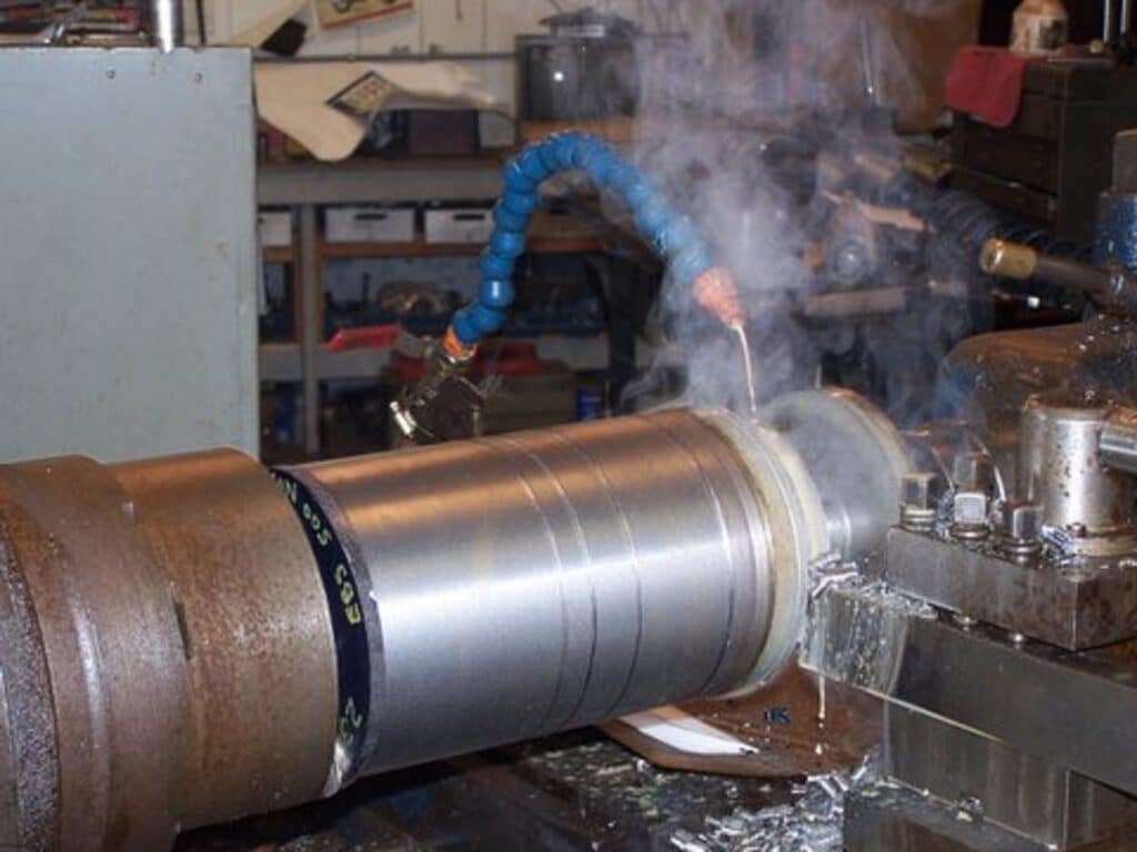
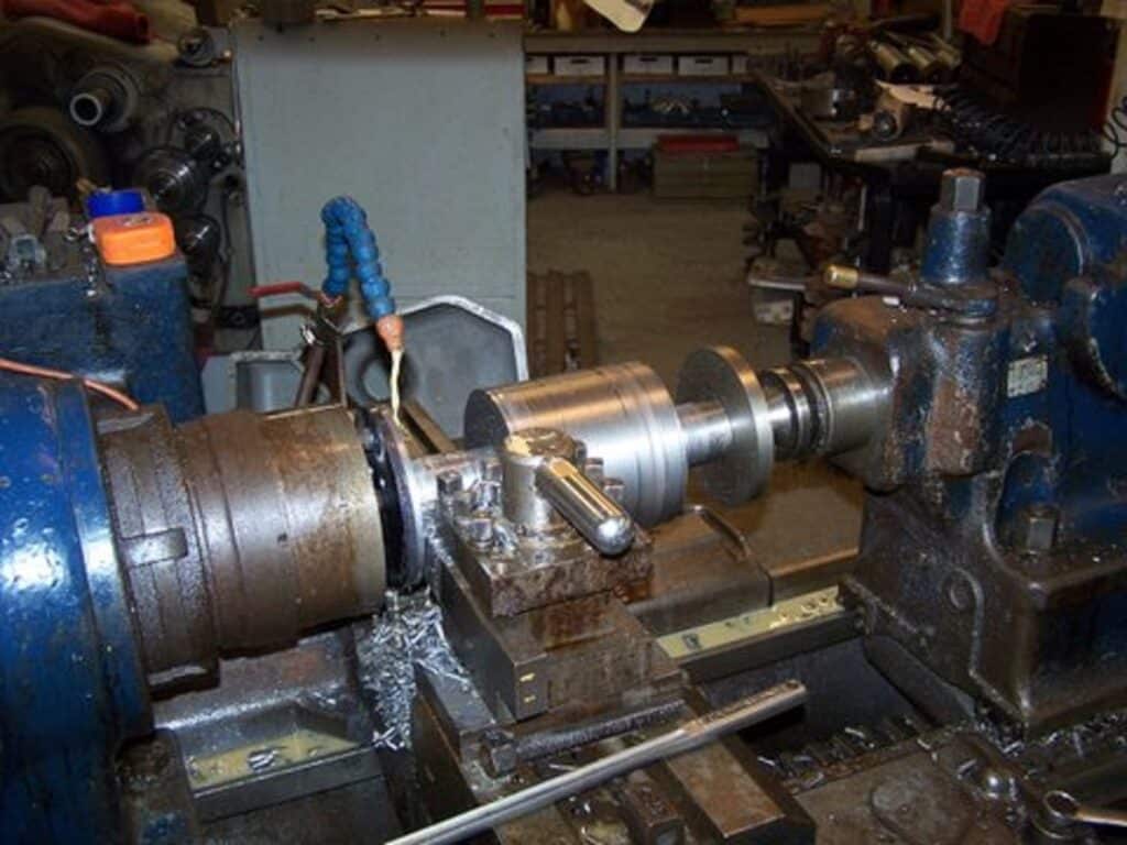
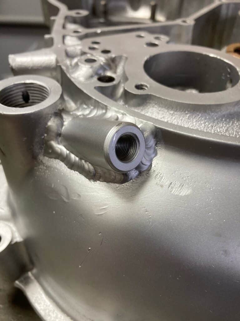
The first thing we did after getting the cases back from cleaning and vapor blasting was to locate the slight bulge in the TS case that runs in a direct straight line from the pressure side of the oil pump to the bottom of the pressure relief valve. I made a small bung that straddled this bulge and center drilled it to 15/64”, the approximate size of the oil passage way. After a little grind on the bottom and side of the bung, I was able to center it over the case oil passage way. We then marked this spot, drilled the case to tap into the supply flow. Then we cut the top of the bung off roughly 1/8” proud of the case. Using the same drill to align the bung over the hole in the case we just drilled, the bung was welded all around onto the case and milled flush with the case. Once again we used Shawn Campbell of NarleyFab to do the welding. Hopefully I can find some blown up cases to practice my aluminum welding for future projects. This is the start of the process of changing the direction of the oil flow to the end of the crankshaft.
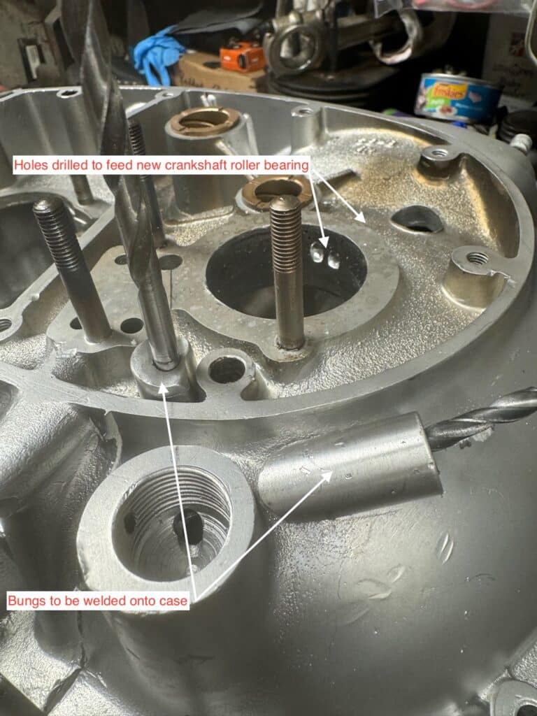
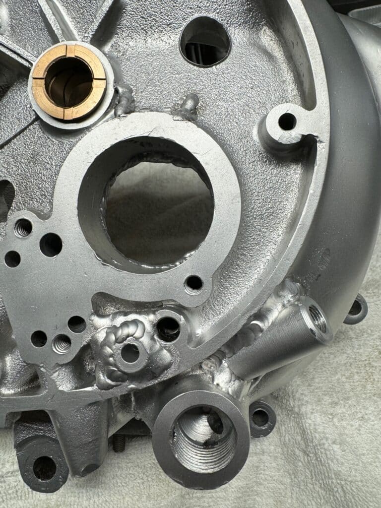
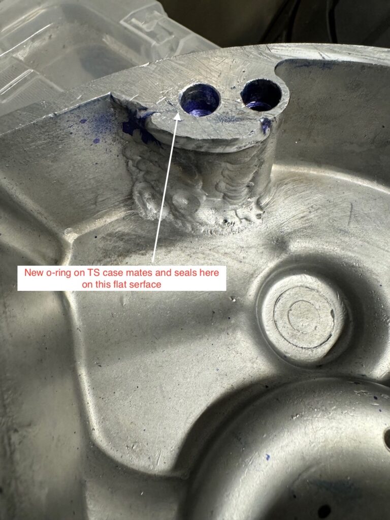
After milling the newly welded bung flush to the case, we had to get the oil flow to travel through the timing cover case. This was done by inserting a metal sleeve into the newly welded bung on the TS engine case that extends into the timing cover case. An o-ring goes around this sleeve to seal the two cases so we spot-faced a grove for the o-ring into the TS case. Another special bung was made and welded into the timing cover case for the new path of the oil flow and for the o-ring to seal against.
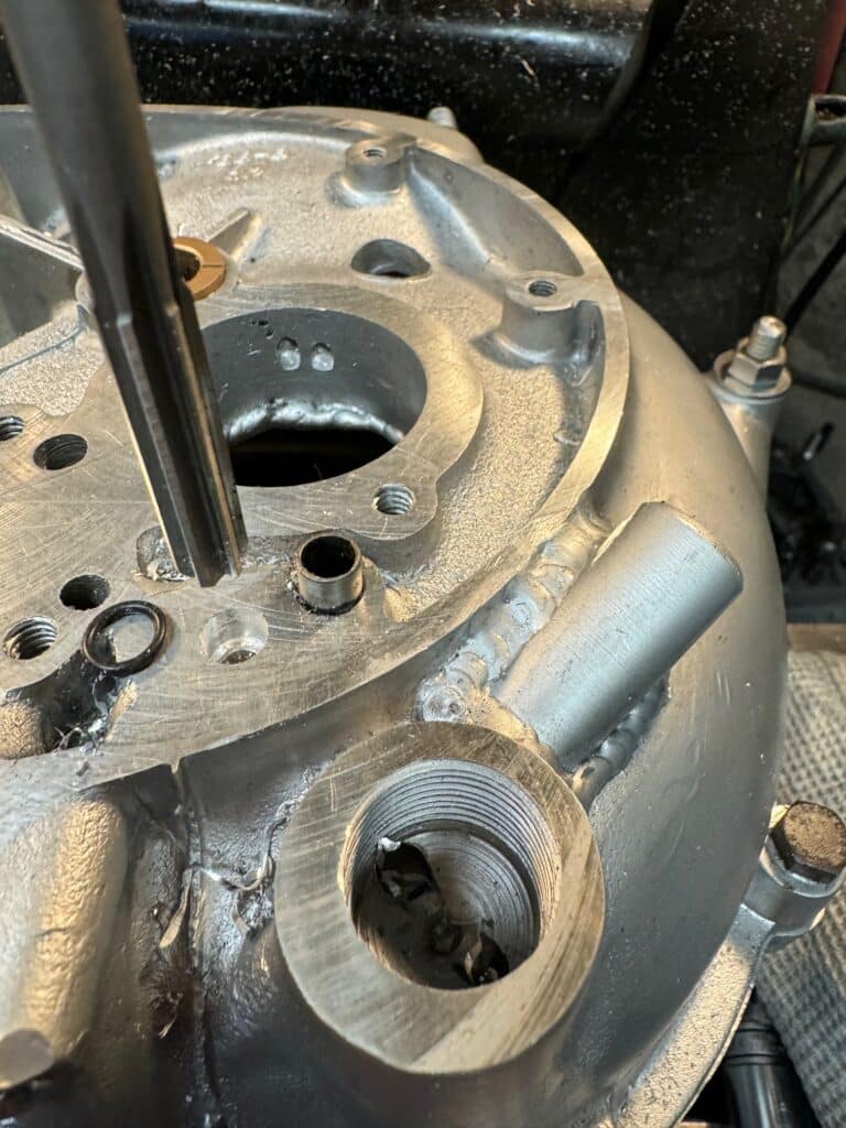
Since this engine is an early version of an A65, I made another modification in order to be able to use an oil pressure gauge on the handlebars. I turned another bung, drilled it with the same size drill, tapped one end to 1/8” pipe thread, and cut the other end at a sharp angle. We then located where the end of this bung touched the case and angled a drill, aiming for the bottom of the oil pressure relief valve hole. This turned out to be difficult and even though we started with a 1/8” drill, our angle was off just enough to protrude into the crankcase. We were able to find an extra long drill in order to get the proper angle, but now we have to weld up a small hole on the inside of the crankcase to maintain oil pressure. In reality, this only happened because we wanted to have an oil pressure gauge and early cases don’t have this fitting. Most other BSA’s do, so this might be moot on your conversion.
We also drilled two holes with large flares at the top of them, to the center of the new TS bearing race. This will allow oil to flow by gravity onto the new TS roller bearing, which is only oiled by “splash” from the crank, rods, and timing gears otherwise. Roller bearings don’t need lots of oil, but they do need some constantly oiling them. This is how the DS roller is lubricated.
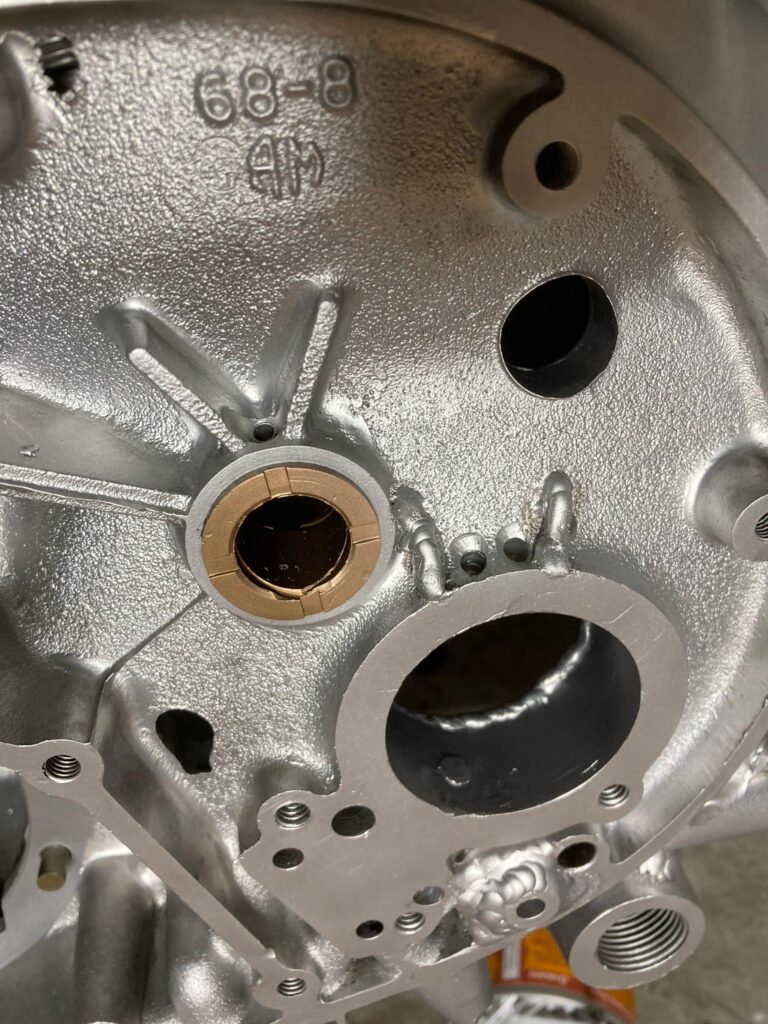
We are also building up the inside of the TS case with weld next to the bearing, in order to machine it flat for trust washers that will enable us to set the crankshaft endplay to the proper clearance. Previously, if equipped with a DS roller bearing, thrust clearance was set by the shell of the TS bushing and spacers. (If it was equipped with a ball bearing on the DS, the balls that were captured in the inner and outer races controlled the end play of the crankshaft.) Round flat steel shims will be added or removed until the proper clearance is obtained.
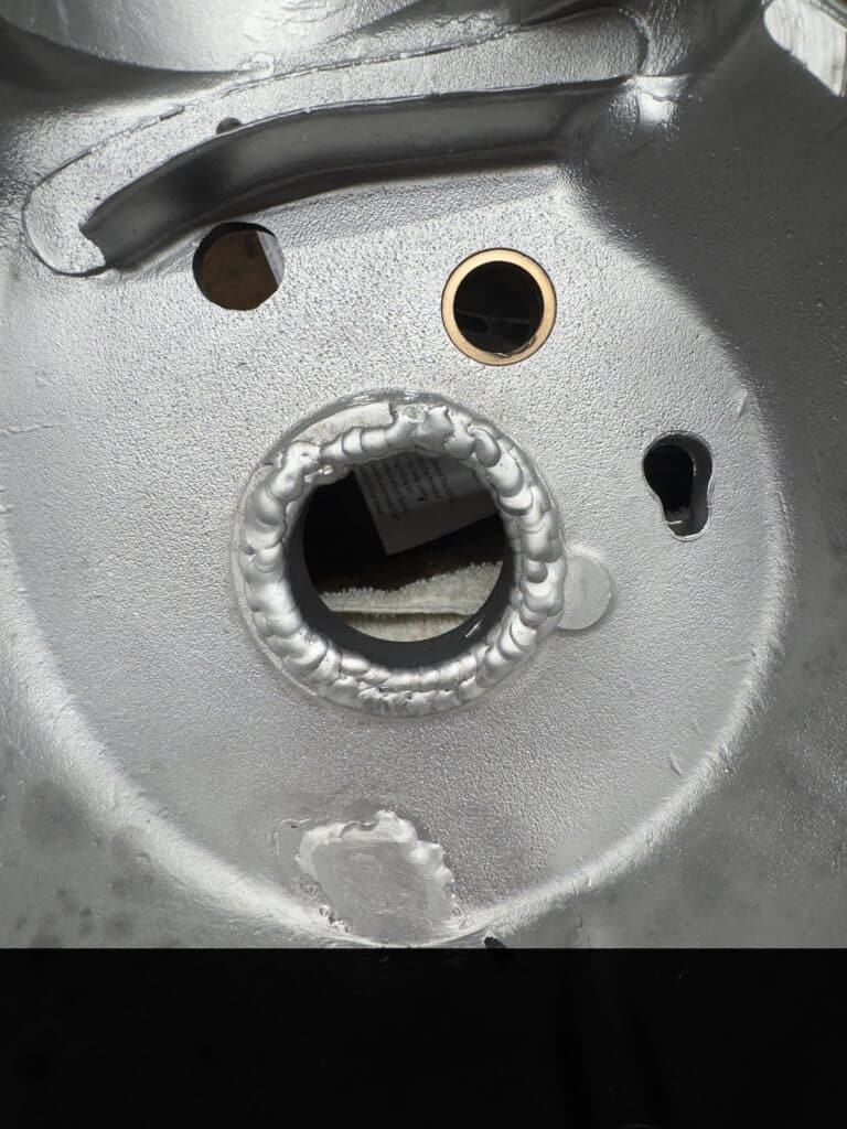
Built up weld to be milled flat for thrust washers

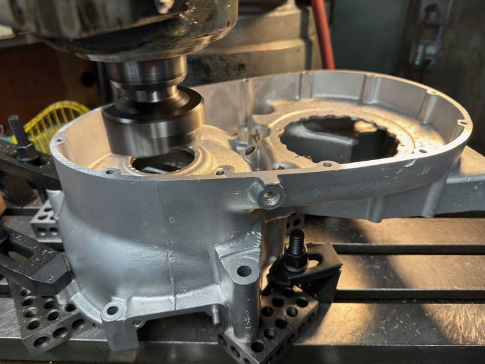
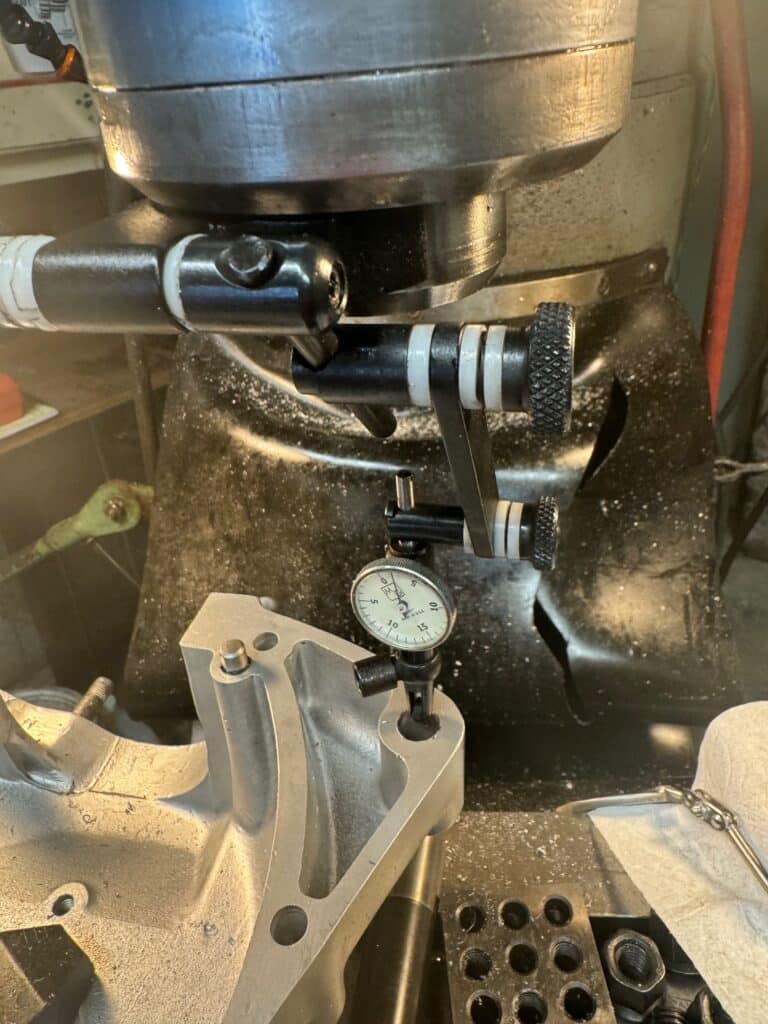
Another modification we are performing is what I used to call “blueprinting” an engine, back in the day. Maybe it’s still called this, but in any event, we are attempting to get every part to fit as perfectly as we can, with the least friction, best clearances, and get the most power. Technically, we don’t have to do all this set-up and work for a TS roller conversion, but maximum performance is our goal. To accomplish this, we first took a good condition flat 2×6 inch fine sharpening stone and ran it over the mill table of the Bridgeport lightly, using WD-40, to remove any burrs. We then cleaned the table and “tramed” it, (running a dial indicator in a circle from the spindle with a special attachment) in order for the mill head to be adjusted and set exactly 90 degrees to the table in a 365-degree circle. Traming the cutting head exactly to the mill table is a crucial step in accurate work, and it should not be taken for granite that everything is is square and true.
Next, we placed the DS case down on 1-2-3 blocks at the center seam and clamped everything down. Since we intend to line bore the cases for new oversized roller bearings, the center seam of the cases is going to be our “dead true” starting point. All additional milling will be exactly parallel or 90 degrees to the center seam. Then we indicated the outside of the case and milled (about .012″ on this motor)off the case, the minimum amount to achieve flatness with this case. Most of the material came off the rear end of the case, and now it was flat and parallel to the center seam. We machined the sides of the cases flat and parallel, so that the line bore for the crankshaft will be exactly 90 degrees to the sides of the cases. We also plan to clamp the newly cut side of the cases to an angle plate that was zeroed out with a dial indicator, then mill the top of the cases (decking) where the cylinder barrels sit, so they are also 90 degrees to the side of the cases and exactly parallel to the crankshaft.
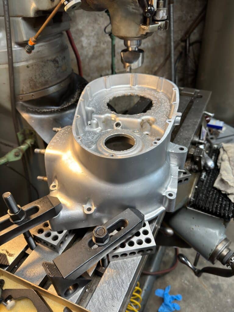
We clamped the newly machined DS case directly to the table and then bolted the TS case to the DS, in order to machine the TS case flat and parallel to the DS case. After indicating how much would be needed to remove, about .009″, again mostly from the rear part of the case. Milling the TS case flat also milled the bung flat for the TS outer case to mate with the timing cover case. All this work was setting us up for a very true 90-degree line bore for the crank.
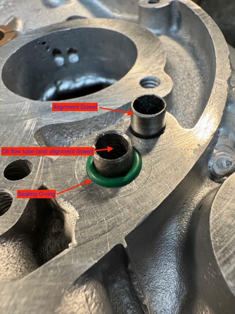
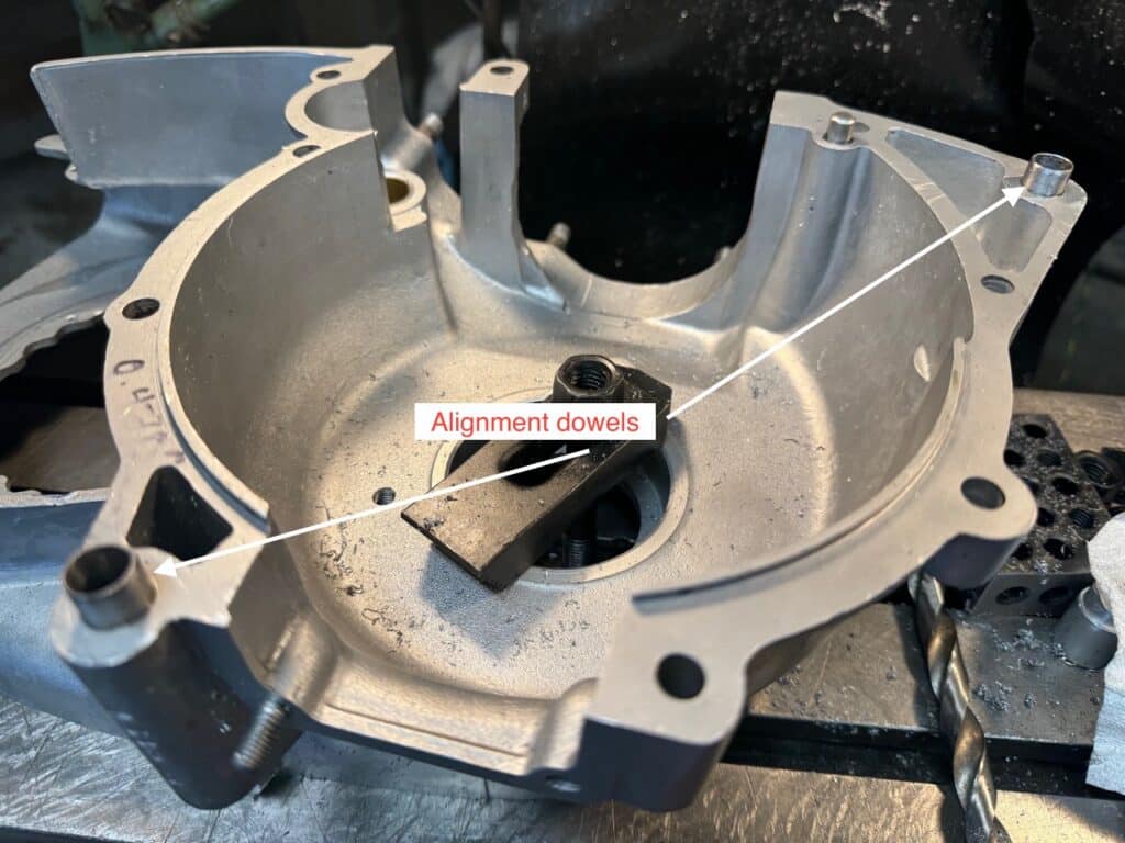
The last step before we start the line boring is to dowel the cases together with round steel tubes that insure the cases fit each other exactly the same way every time they are removed. This is another critical step as unless this is done, the cases have movement with each other. We were able to rotate the cases about .012” (.006″ in each direction) before we doweled them. This movement would throw off our line bore as well as the cam bearing bores. Possibly later cases had alignment dowels. Mine did not, but now does. We indicated the case holes where the dowels go, turned the dowels on the lathe and pressed them in place. After indicating the matching holes in the mating case, we drilled it for the alignment dowels to match up with each other and hold the two case halves tightly without any movement.
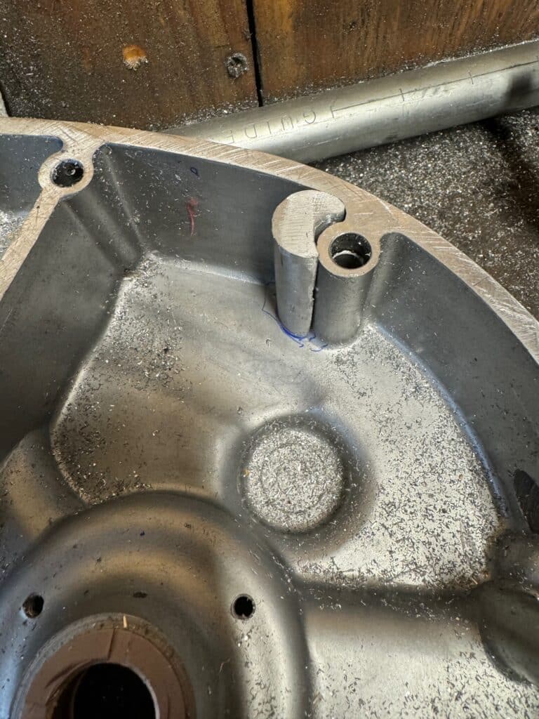
The timing cover case has to have some welding built up on it so it can be mated to the TS case and the oil passage continued through it as shown below. We are now ready to line bore the cases for a new larger Norton roller bearing on the DS and a new (also larger bore) roller bearing on the TS. With the same setup on the mill, we will also bore the timing cover case for the crankshaft to protrude through to accept the new oil flow route. Both the DS bearing and the TS bearing have a slightly larger outside diameter than the stock bearing. This allows us to be sure that the line bore is true when we fit the crank. We cannot continue with the oil flow modification until the crankshaft is fitted and installed. To be continued……..

Absolutely amazing attention to detail. Love the high resolution pictures.
It’s a fascinating project guys.
All the best
Kevin K