June 8, 2024
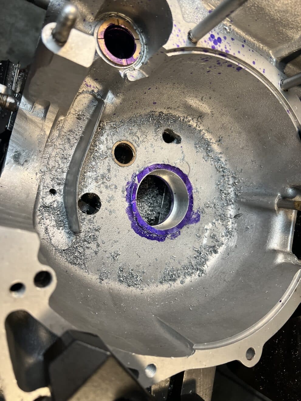
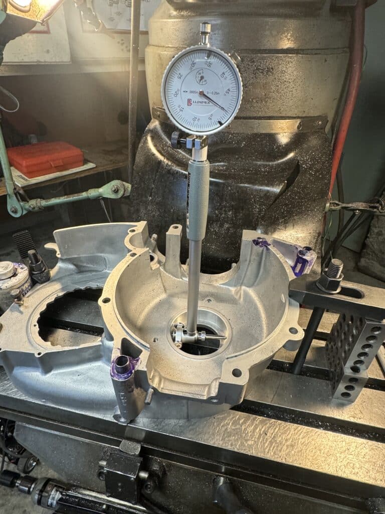
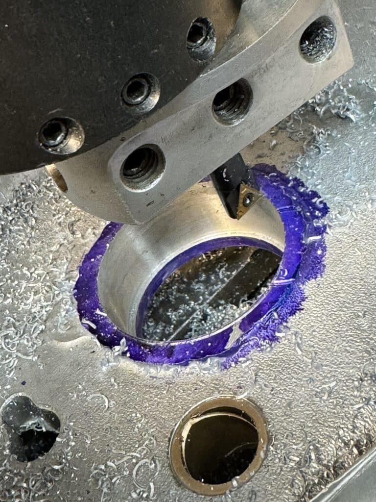
We started the line boring by bolting the drive side (DS) case to the mill table and indicating the existing bearing bore to find the centerline. We locked the table in both the X and Y-axis and then measured the outside diameter (OD) of the new slightly larger Norton roller bearing race (FAG Bearing Part # NJ306-E-XL-M1-C3). This race must be pressed into the case and we are allowing .001” per inch of the bearing diameter for the press fit clearance. Using the bearing measurement and deducting the amount for the press fit, we transferred that measurement to a dial bore gauge and started out with a light cut. Once we had a round bore, we checked it for size with the dial bore gauge, which told us how much material was remaining that needed to be removed. With a few light successive cuts, we reached the final bore size for a press fit. Since the Norton bearing is thinner, I turned a .064″ spacer (the difference in the thickness of the BSA and Norton bearings) to be placed behind it in order to have the centerline of the new crankshaft sit exactly on the centerline of the cases at their center seam.
Without moving the table, which was still locked in the X and Y-axis, we bolted the timing side (TS) case to the DS case to bore that side for the new roller bearing. We were going to use a Torrington needle roller bearing, but then decided to use an NKIS30-SKF bearing which is slightly larger and a more robust roller bearing. The Torrington bearing is smaller but wider than the SKF bearing and would have required us to screw in some thrust stops, since it is the width of the entire bore in the case. The larger OD of the SKF bearing, but slightly narrower width, means that we can now make the bore the width of the bearing and use a step in the case for a thrust stop. This seemed like a win-win for us so I ordered the SKF bearing. However, this stopped everything until the bearing arrived over three weeks later, since we couldn’t move the locked table on the mill. Even with the digital readout (DRO) on the mill, I still didn’t want to move the mill table.
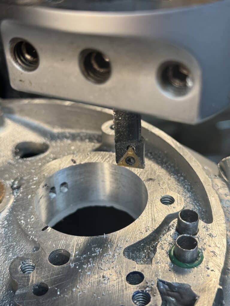
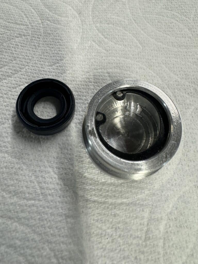
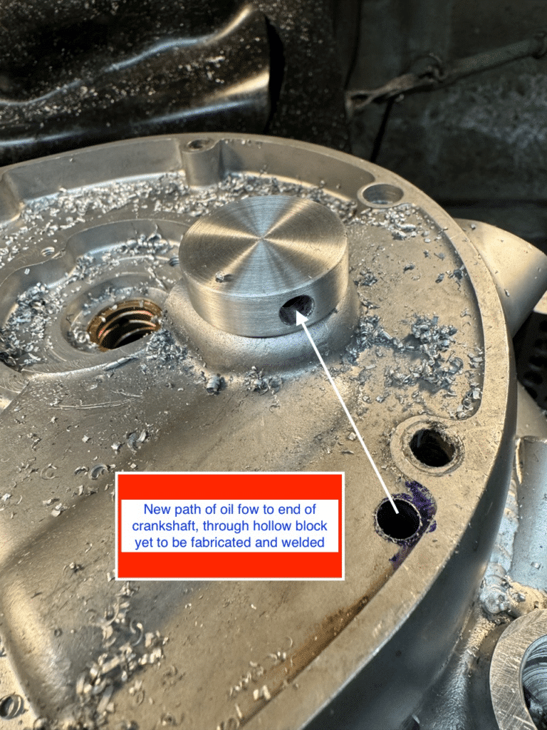
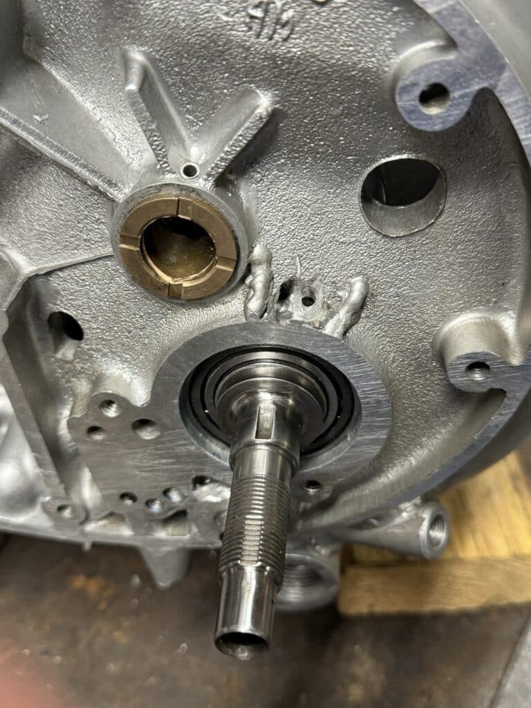
We decided we could make a little more progress with this same set-up, so I bolted the timing cover case to the TS case. Then with the lathe, I turned the cap which will be welded to the case. The cap will hold a 6mm rotary oil seal which will fit over the end of the crankshaft, held in place with a retaining circlip, and will have a hole in it behind the seal for the oil flow to the end of the new crankshaft. I made it 1-1/4” OD, stepped down to 1-1/8”. This cap sits on the same centerline as the crankshaft. I center-drilled the case, drilled it to about ¾” and then used a boring bar to bring it to 1-1/8″ for a tight fit. The cap will be welded to the case along with the hollow connecting part to complete the pathway of the oil flow. BUT, to complete this operation, we need to fit the new crankshaft and for this we need the SKF bearing. The mill was tied up until finally we got this part.
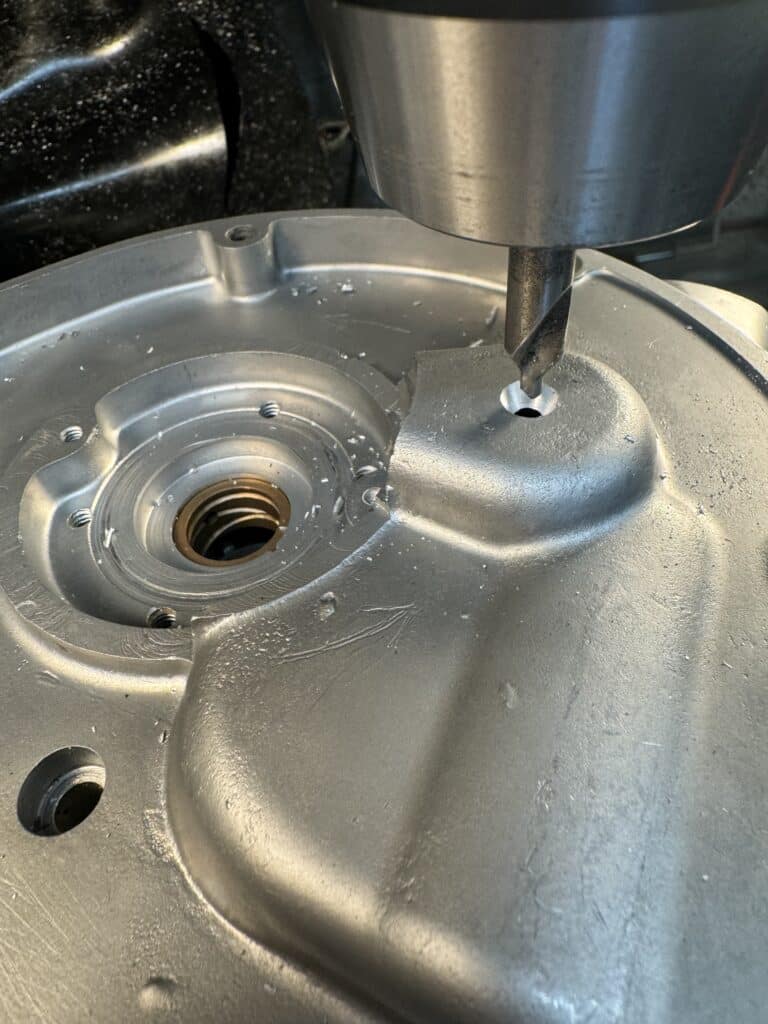
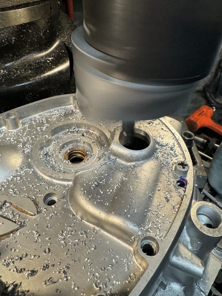
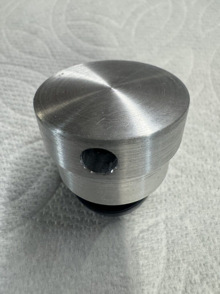
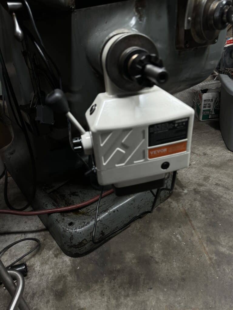
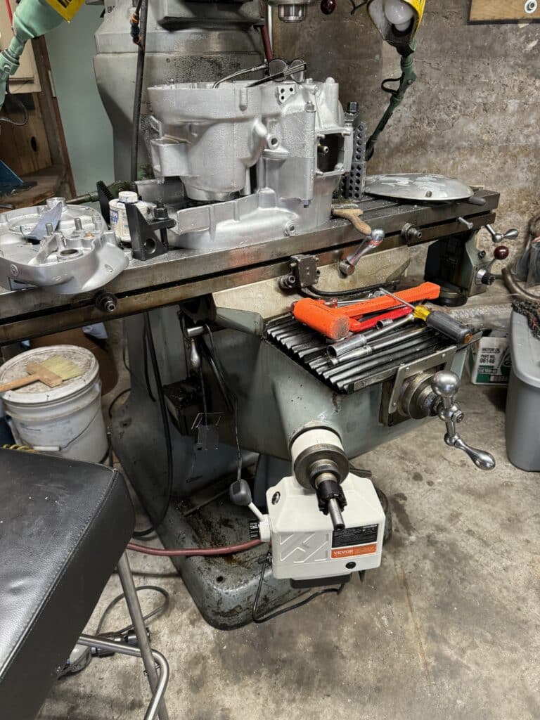
It’s not like we ran out of things to do, though. One of my least favorite chores is cranking the knee of the mill up and down. We have an attachment for a drill motor to do this, but it is not part of the mill and is second choice to a power feed. So after looking at five or six YouTube episodes on z-axis power feeds, I bought one from Vevor, a Chinese company. It is relatively inexpensive and is badged under several different names for the identical drive. At $140 I figured I could buy three of them for the next jump in price/quality and 6 of them for the jump after that. It fits a Bridgeport and several clones, but it isn’t a direct bolt on. Depending on the mill, every installation video I watched had slightly different issues. Within a few hours and some minor lathe work we now have a power feed. It still needs the height limit stop switches mounted on the mill, but the other hand, we were still waiting for the bearing! Since both my shoulders have been replaced, I’m excited about this addition. It isn’t bad for the money. I think it’s slightly slower bringing the table up rather than down, but I expect I’ll use the power feed on the quill for boring operations most of the time anyway. All in all, I really like this addition.
When the bearing finally arrived from France, we went to work on the TS case. First, after bolting both halves of the cases together while still centered on the DS bearing bore, I took a light cleanup cut with the boring bar on the timing side case in order to insure a round bore on the same plane as the opposite bearing. We then had to take apart the set-up and bolt the TS case to the mill for its final bore. I needed to have a step cut into the case for the new SKF bearing, and doing this on the down stroke is extremely difficult. Since the tool cutter is a triangle shape, cutting a step in the case on an up stroke woud have left a 33 degree step and I needed a 90 degree step. It would have required grinding a special boring tool and a LOT of trial and error. So we turned the case over, bolted it down, carefully indicated the crankshaft bore to within .0001”, and locked the table. We set the depth stop for the width of the new 22mm wide bearing, bored it to the final size for a press fit, and installed it in the case. This bearing sits flush with the inside of the case and spacers (thickness yet to be determined) will be used here to get the final clearance for thrust end play of the crankshaft.
Before we could install the crankshaft in the cases, a pair of spacers had to be made and pressed onto the crankshaft. Both bearings we used have a slightly larger ID’s than the crankshaft so two thin spacers (one for each side) had to be pressed onto the crankshaft to make up this difference. I made them out of 4340 steel, the same material as the crank itself , and using Loctite bearing retainer, pressed them onto the crank.
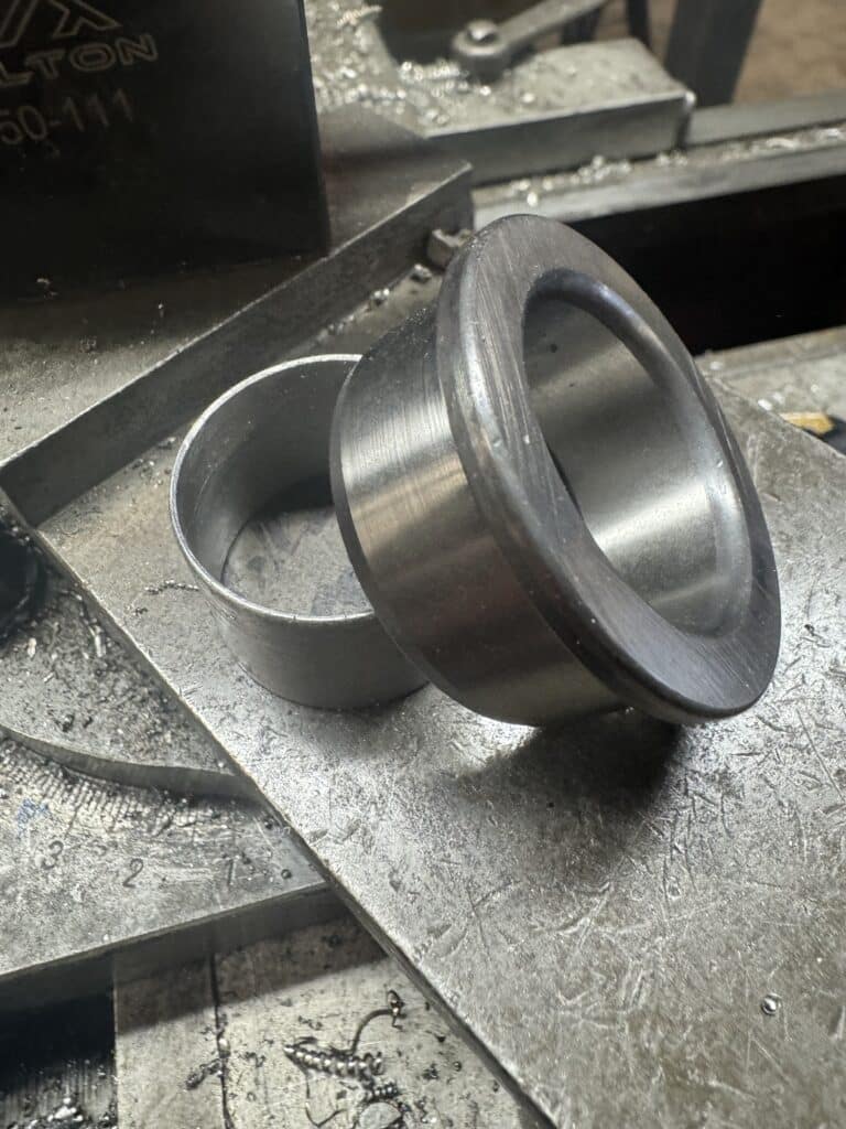
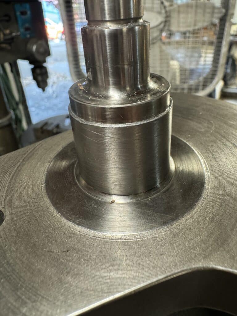
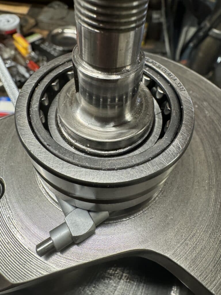
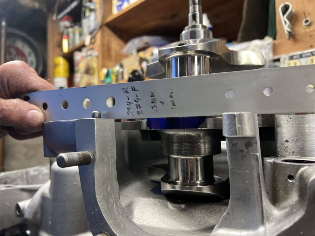
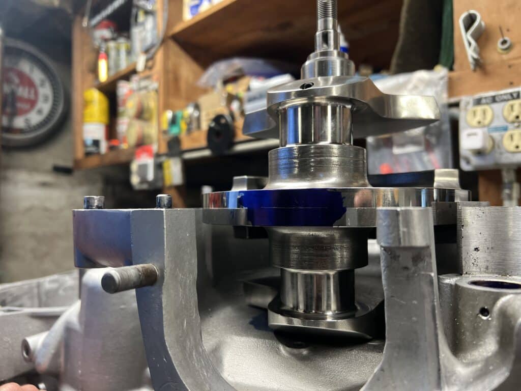
Now we were ready for the first trial fit. We pressed the inner bearing races onto the crankshaft over the new spacers. Placing the crankshaft in the roller bearings and pushing the cases together, we were both amazed with how little effort it took to spin the crank on the new line-bored cases with roller bearings on either side. Now we can measure how much side-to-side clearance there is with the crank installed and the cases torqued together. We will use a dial indicator to measure this and make or buy the appropriate spacers, leaving about .002” to .003”for thrust clearance.
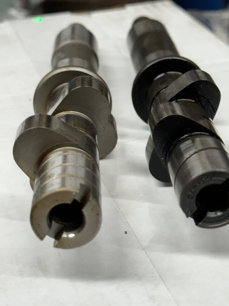
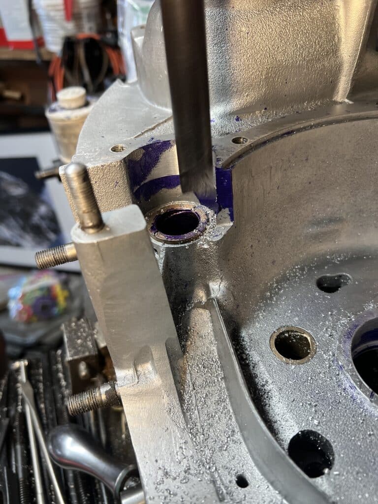
A couple of other minor (I hope) issues came up along the way. Both have to do with different parts being used and your build may not have these issues. The first was the clearance between the cases and the cam lobes with the new higher lift cam. Indicating the cam bearings gave us the centerline for the cam and we enlarged the cam lobe clearance to about .040 for the new cam using a boring bar. Next, although the crankshaft spins VERY freely, there was a very slight rubbing for part of its rotation. Using blue marking dye, there we found a couple of spots where the crankshaft is just slightly rubbing on the cases. This is a simple fix by grinding some metal away, but of course we had to take the new bearings out of the cases to do this work, then re-install them to check the clearances again. Both these issues would not be there with a stock crank, stock cam, or one with slightly less lift. While we are grinding the clearances for the crank, we will also grind any casting seams away on the inside of the cases for removing any future stress cracks before they happen.
When the cases are finally bolted together with the proper thrust spacers in place, we will continue to finalize the work needed for the flow of oil to the end of the crank.

Comments