
12/4/25
The Bob Newby clutch saga didn’t end when I re-cut the clutch hub taper to match the BSA transmission main shaft taper. Yes, this solved the taper fit issues and I was able to move the clutch basket in about ¼” which aligned the drive belt much better as well as taking more strain off the main-shaft, but now we found other issues. The first issue was that now the rod that actuates the clutch pressure plate was now ¼” too long. This was easily fixed by just cutting off ¼” from the rod, heating the tip red and quenching it to re-harden the tip. The next issue involved the belt drive-hub width. It’s thicker than the combined width of the old triple-chain, drive sprocket, and rotor drive plate, also by about ¼”, so the studs that hold the alternator stator were too short by about ¼”. Additionally, we couldn’t even use the rotor drive plate because it was driven by the spline on the crankshaft and the spline is now completely covered up by the new wider drive belt hub.
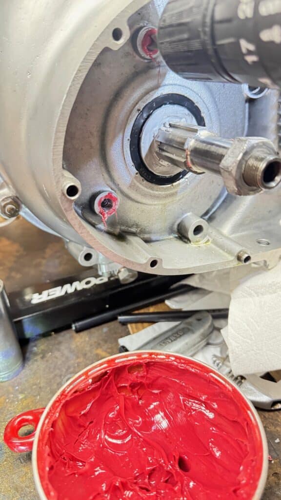
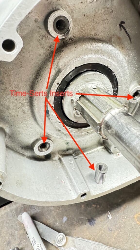
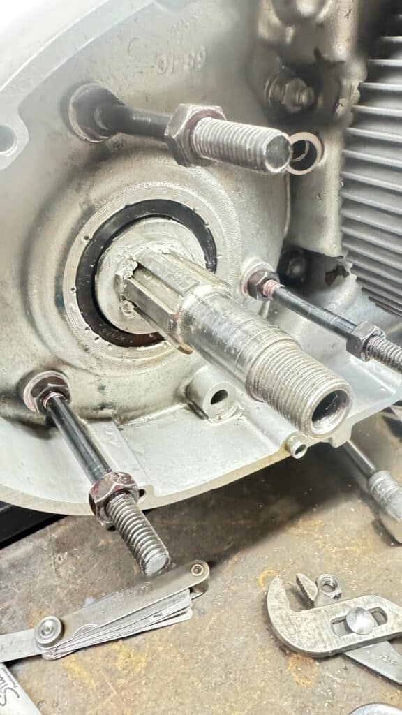
This fix involved buying longer 5/16” studs from McMaster-Carr. Installing them was more complicated because this motor uses Witworth (British Standard) threads on all the nuts and bolts. I change to SAE (Imperial threads) as needed and on almost all new parts, if I can. The British stopped using Witworth threads around 1968 on motorcycles, switched to SAE for a few years and then went to Metric. Some of their later bikes had all three thread standards, meaning three different tool sets were required to work on them. My bike falls into this category. Our problem was that we had to install SAE 5/16’x18 studs into a 5/16”x26 Witworth tapped hole. SAE (and Metric) threading uses a 60° thread pitch while the Witworth system uses a 55° pitch. Our choice was to either drill out and re-tap the holes and using Helicoil inserts, or drill out and re-tap the holes using a threaded insert called Time-Serts. Both had their own issues. Helicoils have a steel tab for installation that you break off when the coil is installed. Chances were great that breaking off these steel tabs could fall into the motor causing big issues so Heilcoils were out for an assembled motor. Since the alternator stud holes are through holes into the motor crankcase, re-taping them would require special care. Even though the taping chips are aluminum, we didn’t want them going into the crankcase, if possible. Using a thick grease coated all over the drill and tap, we drilled and then re-taped the holes to 3/8” with a special Time-Sert tap, removing the tap every couple of turns and cleaning the metal embedded in the grease from the tap. We repeated this process until we got to the depth we needed and then used several Q-Tips with acetone on each hole for cleanup. Had this been a 1968 BSA or later, the new longer SAE studs would have fit perfectly.
There were no instructions included in the box with this clutch. Not one word was said on Bob Newby’s webpage about a hub width wider than stock, or longer studs being needed for installation of the alternator with his clutch. His webpage is the most minimalist webpage imaginable. The homepage has a photo of his clutch with no links to anything else and his products page also has no links or information. A contact page and a brief bio is all there is. If there had been information warning about stud length, or even installation instructions, I would have changed the alternator hole threading before engine assembly. Newby’s website lacks any information about this or what is needed to make the new part work along with an alternator. You discover what you need to know as you move along with the installation process. What a great feature! One would think that if a product was not a direct replacement fit, that somewhere instructions on his website would mention this.
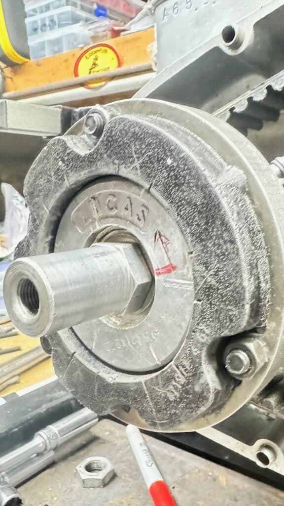
Finally with the longer studs installed using red Loctite, the crankshaft threads were now about ¼” too short to secure the rotor especially with my outrigger bearing modification. My fix was to machine a ¼” recess into the rotor magnets. Hopefully this won’t affect the magnets in the rotor, but I won’t find this out until the motor runs, or in my case with an ET (energy transfer) ignition, IF the motor runs, as only functioning alternator will allow the motor to run at all.
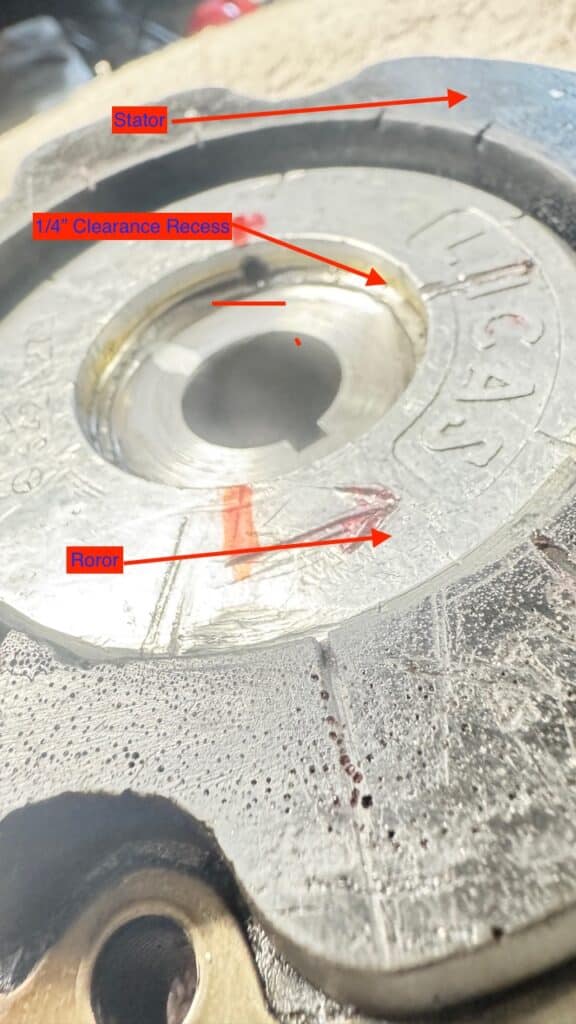
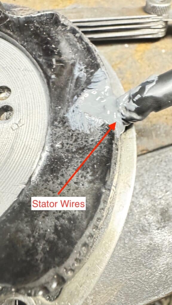
I couldn’t use the rotor drive plate to turn the altenator rotor because the spline that drove the rotor drive plate was now covered by the wider Newby drive hub. I was able to drive the rotor by a keyway cut in the rotor, but I needed to cut a new keyway into the rotor to phase it for maximum charge, timed with the ignition points just opening. With an ET ignition, it is important to get the points to break (sending the current to the coil and spark plugs) at the time of maximun charge between the rotor and the stator, hence, phasing the rotor. This new keyway also would serve to drive the alternator rotor. Additionally, with Newby’s wider drive nub, the wires exiting the backside of the alternator stator ran right into the spinning hub. As a last modification (we hope), we carefully cut away some of the epoxy covering on the stator with a razor knife to expose the wires and changed the wire exit angle by 90°. The wires now exit out the top of the stator and clear the drive hub. We filled the void this created in the stator with JB Weld epoxy to protect where we exposed the wires and hold the wires in place. I can’t imagine the effort and expense someone would have to go through to install a Newby clutch without our equipment or machining skills. Although there is a lot to like about the build quality of this clutch, proper fit and installation are difficult at best.
Next we had to lengthen the exhaust push rods by about 0.140” for proper fit of the valve train. The intake push-rod length was fine, so we got some 2024 aluminum tube and push-rod ends from Jim Schmidt to make longer push-rods for the exhaust valves. This length was needed most likely because of the new exhaust seats in the head and or sinking the valves slightly to gain the clearance we needed when both valves are open (overlap) at the end the exhaust stroke. They were fairly easy to make and assemble, and they solved the issue.

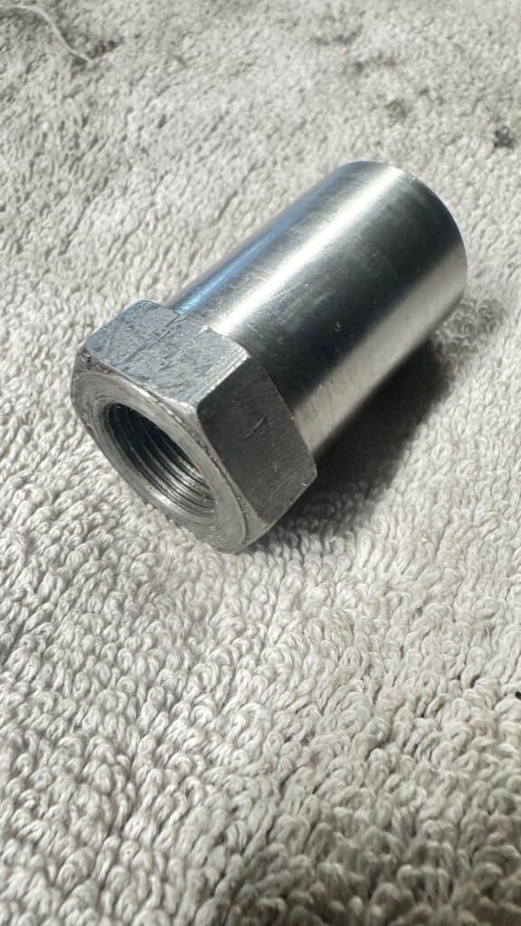
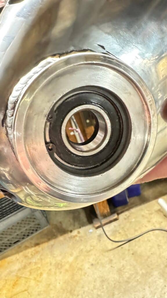
The last three things we did to the motor on the workbench were to adjust the valve clearance, find top dead center with a degree wheel, adjust the points gap and time the ignition points. With the points just opening, we phased the alternator rotor with the stator for maximum charge and marked the rotor so that it lined up with the crankshaft keyway. We cut a new key slot in the rotor to complete this task and tightened the rotor nut, machined from 4340 steel, the same metal as the crankshaft. The crankshaft nut now doubles as a crankshaft extension for extra support, entering the outrigger bearing machined into the primary case.
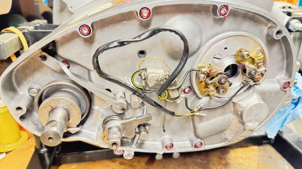

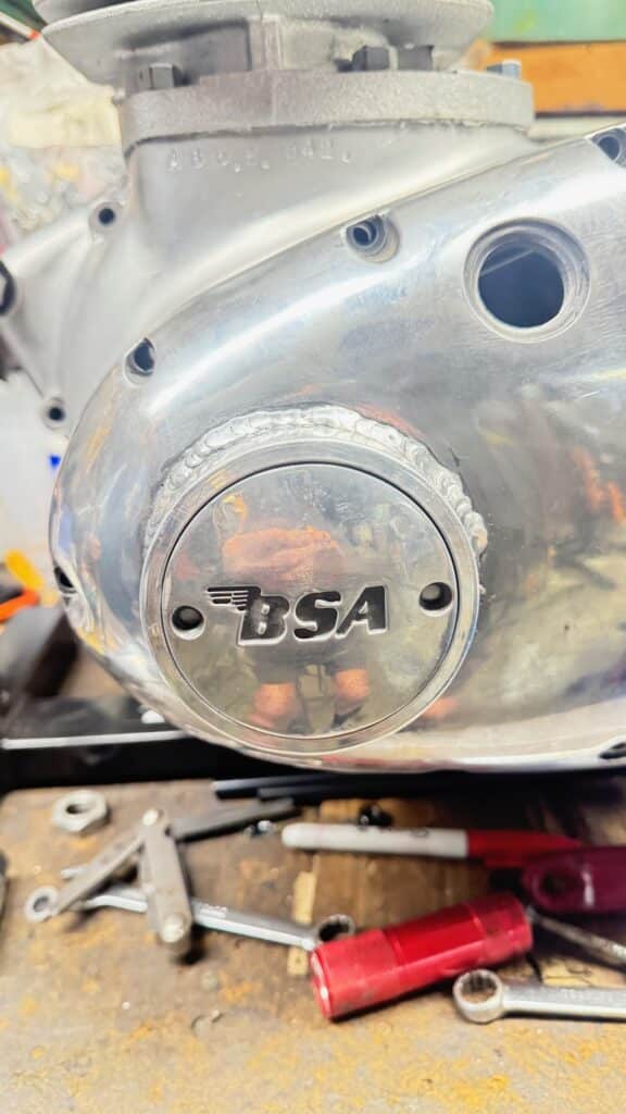
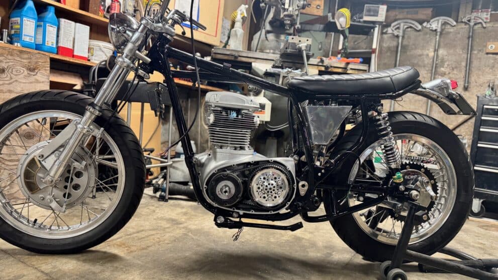
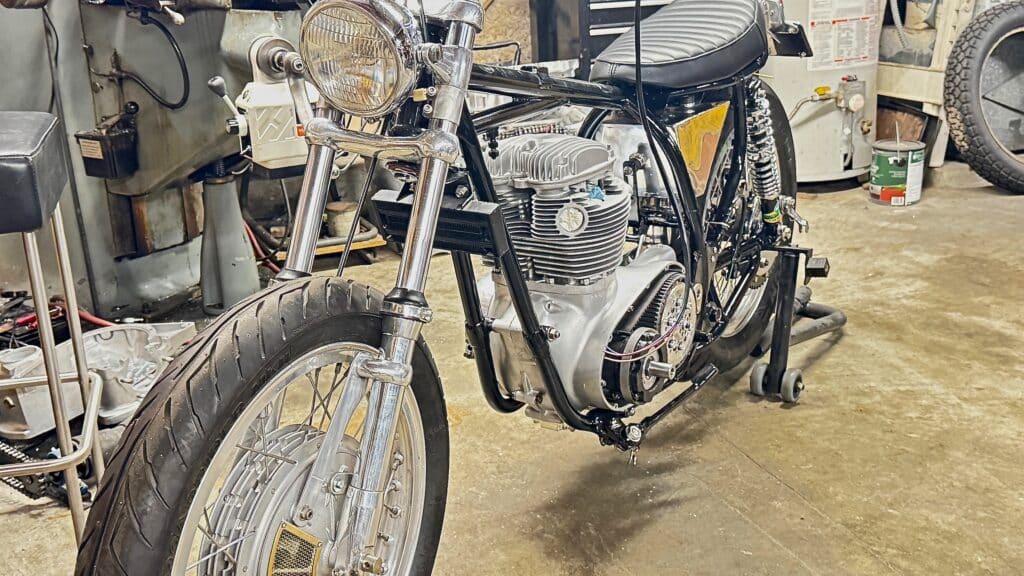
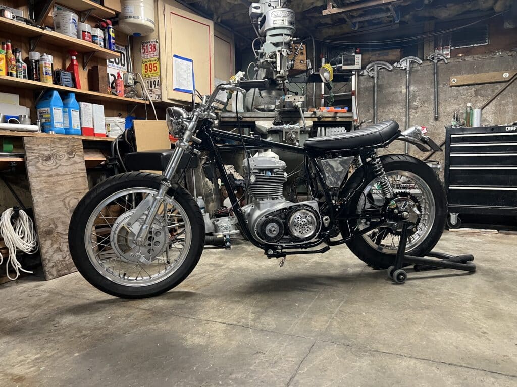
The motor is now back into the frame. There is still much to do such as building an exhaust system, carburetor manifolds, wiring, hoses. oil, fuel, and vent lines etc.

Larry & son, thank you again for continuing to send me updates on the BSA project. I’ve also utilized heavy grease on the drill and tap in holding contaminates from going places I didn’t want them infiltrating. My question is how you centered the ID of the outside bearing both perpendicularly and radially when welding on the the extension tube that holds the OD of the bearing on the primary case, and how much run-out was there on the bolted up assembly holding the rotor, and also how did you cut the new keyway into the rotor? If you have the time, I would very much appreciate a phone call in answering my three questions. David Riddle 818-314-7275