
3/3/26
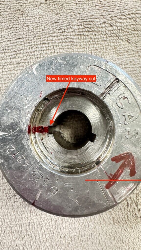
Now that the motor is back in the frame, a few issues had to be worked out. Eric took the alternator rotor over to Jim Dour at Megacycle Cams in San Rafael, CA and Jim broached the rotor with a second keyway slot on our mark, using an arbor press, to align it with our ignition timing (phasing). As explained in our last post, this was needed as a workaround, as the original drive plate for the rotor couldn’t be used because the wider drive hub for the Newby belt-drive clutch covered up the splines on the crankshaft that drove the original drive plate. The Lucas manual has a great graph, and refers to the peak amplitude occurring when “… the interpolar gaps of the rotor are situated on the center lines of the stator limbs”, or within a few degrees of that position.” This is where we broached the keyway in the rotor just as the ignition points opened the circuit to fire the spark plugs.

I had a setback from a fall a few weeks ago where I broke a rib or two and re-injured a groin muscle in my left leg. This has slowed me down greatly for work on the BSA and everything else. Eric has been doing most of the work and I can only watch. I’m slowly healing but the fall is related to my neuromuscular disease CMT. (see BSA Report #2)
Now, a diversion from the BSA.
Things got interrupted for a few weeks when I received a new larger lathe. Over six months ago we started looking at larger lathes to replace my 12” lathe. Although we usually got the accuracy we needed from it, it wasn’t always easy. Lots of tweaking was usually needed because of the lack of rigidity in small lathes. We started doing research on lathes from US companies like Precession Mathews (PM) and Grizzly and soon realized that many if not all these machines originated in China (sometimes Taiwan, the Philippines or somewhere else in Asia), but they came from companies with locations in China and sometimes were assembled in these other locations.
After attempting to communicate with about 4-5 companies in China through Alibaba.com we found one who would build a 14″ lathe to our specs, a C6236K from Tengzhou Sosen Machinery in Shandong Province, China, and also a representative who spoke enough English to allow this process to happen. Several companies we spoke to seemed less flexible than Sosen and wouldn’t supply a machine exactly to my specifications. We accomplished this through several dozen back and forth emails. PM and Grizzly spec their machines in similar fashions from their various suppliers for the different models they offer, and badge them with their names. I typed up a long list of what my requirements were and got a quote for everything, including all taxes, duties, and delivery to my door. I wanted certain features like 240 volt, single phase 4Kw wiring, precision Japanese head-stock bearings, 2-1/8” spindle bore, hardened and precision ground bed ways, 3-Axis Digital Readout (DRO), several chucks including a 5C collet chuck, a taper attachment, and about a full page of other specs. The quote I got back from Tony at Sosen Machinery was over 2/3rds less money than from PM for a similar machine and included duty, taxes and shipping. PM or Grizzly did not include tax or shipping in a similar machine, possibly badged with their logo from the same company. I don’t want to tell you that my new lathe is identical to a PM or Grizzly lathe. I specified what I wanted in my lathe to Sosen Machinery, and short of the issues explained below, got what I asked for.
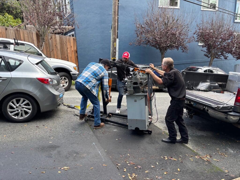
I nervously wired a 25% deposit and was told it would take about 2 months for the custom build. We put my current lathe on the market and finally found an interested party who purchased it. I towed it out of my shop attached to an engine hoist, while Eric and a friend of his, Kelly Green, loaded my old lathe into his truck. Suddenly we were without a lathe.
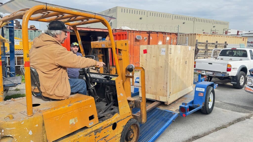
Around Thanksgiving I was told the new lathe was built, so I sent in the balance by wire transfer. I have found that Christmas holidays usually slow things down to a crawl, and we didn’t get the new lathe until the second week of January. A forklift was needed to get it off a delivery truck (3,000 lbs.) so I had had Sosen Machinery deliver it to my friend Dave Capps, who has a glass shop, D.J. Capps Glass in Burlingame, a suburb of San Francisco about 20 miles to the South, and Dave has a fork lift.
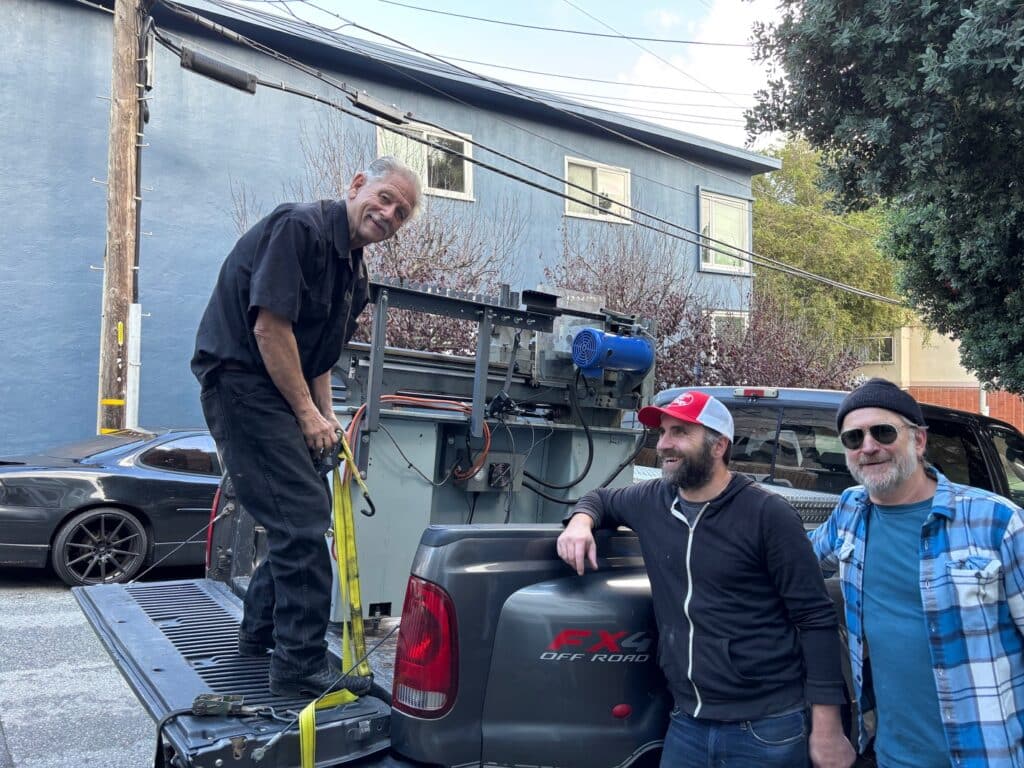
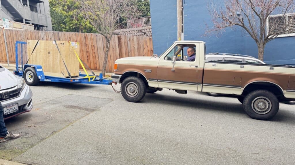
The next day Dave loaded the crate onto the tilting trailer we rented, and using Eric’s 1984 Toyota Tacoma 4×4, we towed it to San Francisco. Neither of us has had much experience backing up a trailer and since I live on a narrow one-way street, also on a fairly steep hill, I called my friend Gordon MacDonald who has trailered boats most of his life. Gordon has a front-mounted hitch on his Ford 4×4 Diesel truck. We transferred the trailer from my son’s truck to Gordon’s truck. Using low range 4-wheel drive, he expertly placed the trailer at the top of my short driveway where we chocked the wheels and unhooked his truck. My wife Nancy directed and diverted traffic from coming down our street for the 10-15 minutes for this operation take place.
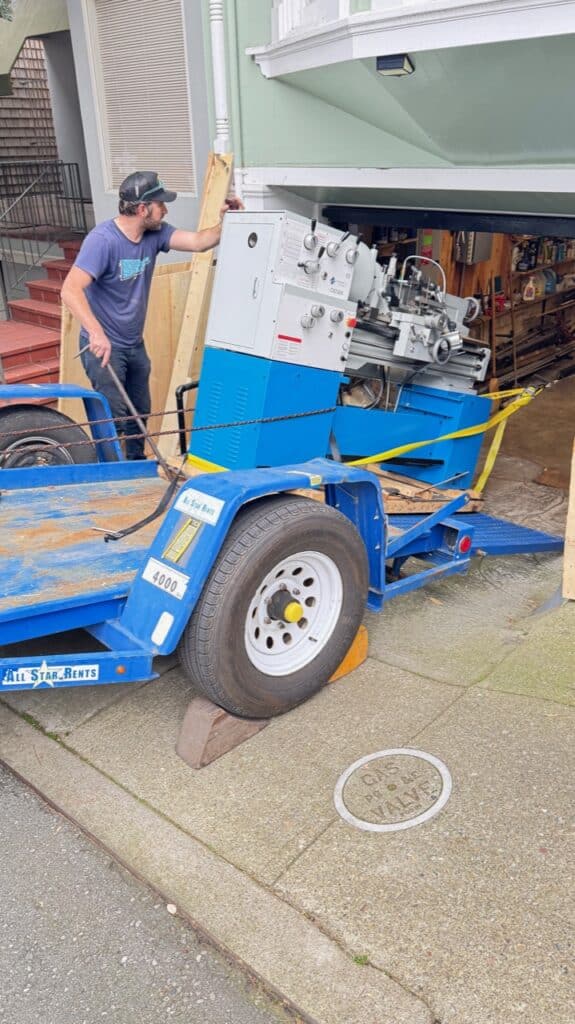
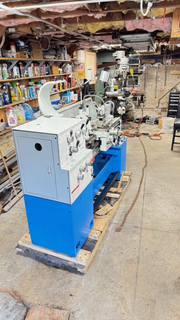
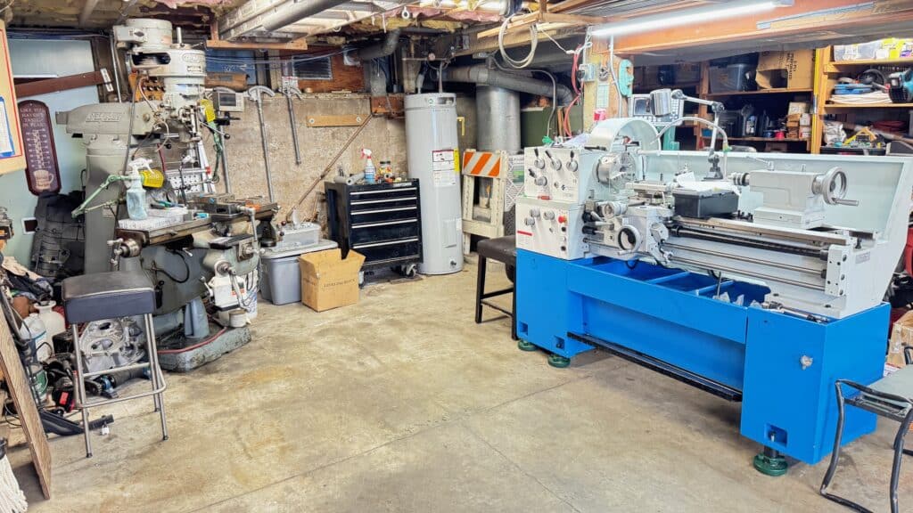
Next we un-crated the machine while still on the trailer, and attached an electric winch to the rear concrete foundation at the rear of my shop. Using the winch, we slowly pulled the lathe off the tilting trailer, still attached to its wooden pallet, down the driveway and onto the flat of the shop floor. With a 2-ton rolling engine hoist, we lifted the lathe slightly, disconnected the pallet bolts, and placed the lathe where we wanted it to go. I wired it, cut some extension pads to level and raise it on my slightly slanted floor, and we had successfully brought in my new machine.
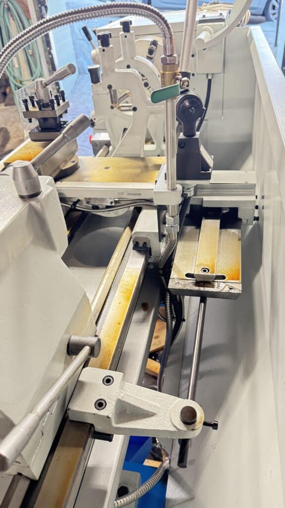
Was it worth all the angst, emails, and time waiting for this lathe? The monetary savings were at least $12,000 over a PM or Grizzly lathe with the same or similar specs, but there are a couple of issues. The first one, which I knew about going in, was that it would be filthy. It was covered in shipping oil which had grit mixed in it from grinding the hardened ways. We wiped off all the oil and grit with rags, but it is impossible to wipe off the parts underneath the compound, cross slide, tailstock and carriage. Even though the lathe now looks clean, we have to take it all apart to clean the packing oil (and grit) and re-oil the ways. Would we have had to do this cleaning on a PM or Grizzly lathe? Who knows? There is now no visible evidence of oil and grit on my lathe after a wipe down, but I know it is there under the cross slide, carriage slide and tailstock, so we will take things apart for through cleaning and oiling. Possibly PM or Grizzly does this in their assembly but one can’t tell without disassembly. I’ll never know, but for over $12.000 difference between lathes, I’ll spend the day taking my new lathe apart for cleaning. The grit underneath the sliding parts is abrasive, and leaving the lathe as is will surely wear down the ways and the lathe will lose accuracy if we don’t take this step. Knowing what I know now, I would do this on a new PM or Grizzly lathe also, if I had purchased on of theirs? Probably, as the cleanliness is unknown until one checks. Here is a link to a guy who purchased a similar lathe as mine showing what he had to do to clean it up his machine https://www.youtube.com/watch?v=tLhHI_mdDuw.
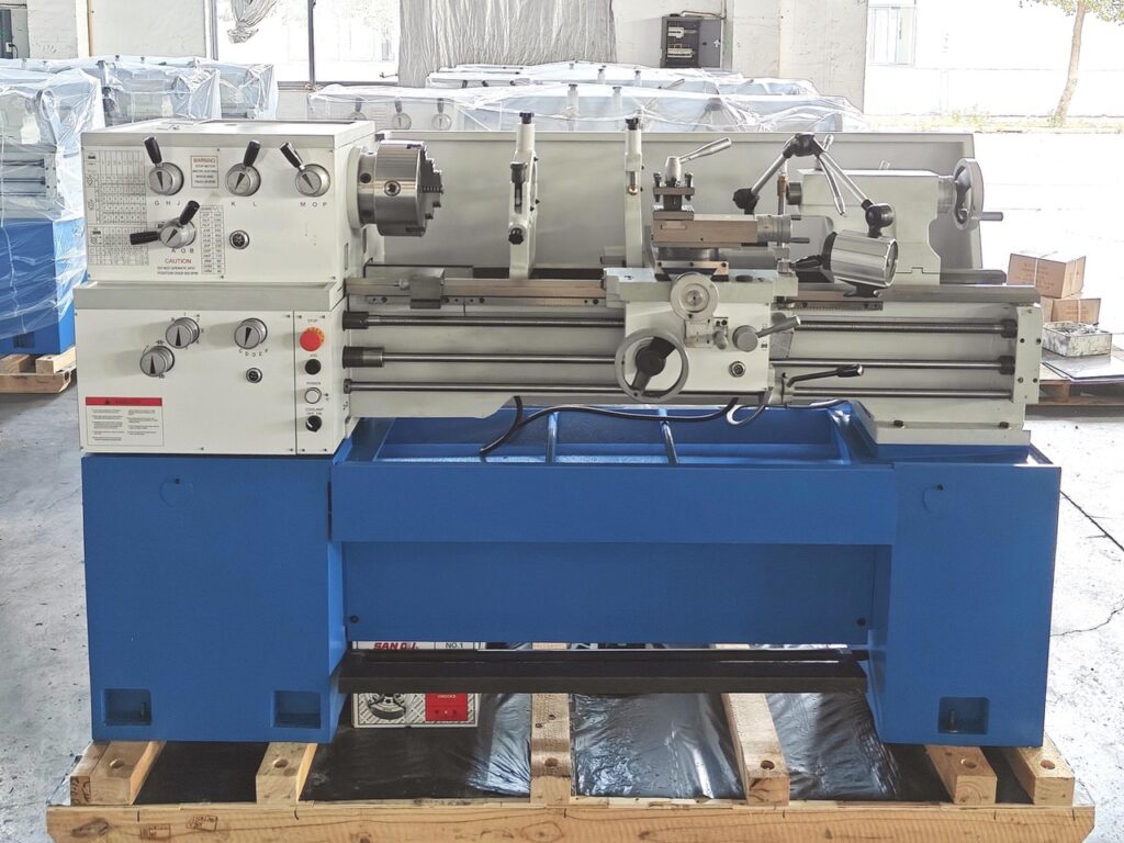
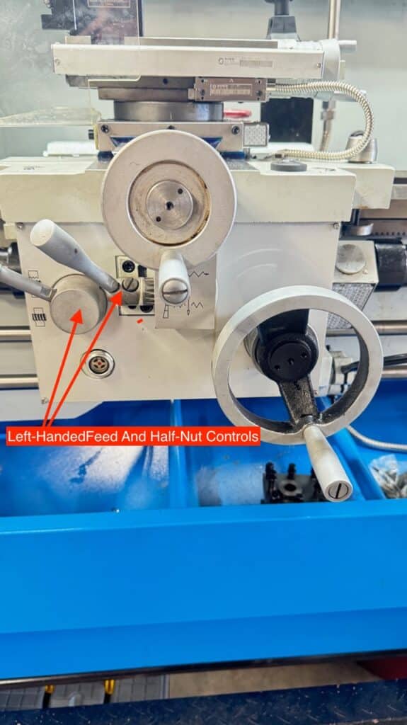
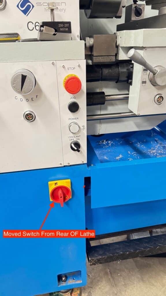
The biggest issue now is that the lathe they shipped me has left-handed feed and threading control levers and I’m right-handed. The photo (above) they sent me along with the specs and contract clearly shows a lathe with right-handed levers. The photo below is the actual lathe they sent me. The fix involves getting an opposite apron casting from China. I wrote them about this, but they are closed until the first of March for Chinese New Year. It looks to me like most of the internal parts will change over and only the apron casting and face-plate need swapping. Other than this mistake and a good cleaning, this is a wonderful machine that easily switches between Imperial and Metric threading and is very ridged. The only other complaint, already easily changed, was extending the power on/off switch wires, in order to move the power switch to the front of the machine for ease of use. The power switch was on the back of the machine, inconvenient to get to, and would have been very hard or impossible if the lathe was placed against a wall. That fix was easy for me and if known beforehand, I could have had them place it on the front. I can’t tell you why it was on the rear of the machine or why I was sent a left handed machine, but both are easily fixable and the lathe is totally usable (although awkward) until the correct apron casting arrives.
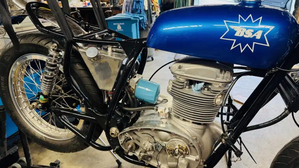
Back to the BSA!
I decided to use different handlebars so we had to shorten the brake cables for the lower bars. I also wanted to start routing oil lines, but realized that many of the brackets, nuts and bolts were fairly grungy, rusted or beat up. So I took these parts to be nickel plated before assembly. Miles at Electro Plating Specialties in Hayward CA, did an excellent job over the Christmas – New Year holiday. With fresh looking parts back on the bike, we begin the process of assembly.
For the intake manifold and carburetor, Eric is designing intake manifolds in CAD that will be sent out for 3-D printing in 6061 Aluminum. It’s a little complicated to figure out all the dimensions, so he is using a 3-D scanning program on his iPhone to assist. We want to use 38mm Mikuni VX carbs that are about an inch longer than the 34mm Mikuni’s that were previously on the bike with a 750cc engine. With the larger 855cc displacement and the porting and flow of the head, we think these carburetors will work well. I was never able to fit an air cleaner on the carbs with the 34mm units, since they were too close to the frame tubes. So Eric’s design will have an offset to turn the carbs outward by roughly 20 degrees to miss the frame, and the air filters will have a 20-degree offset to straighten them out in the opposite direction, keeping them from sticking out too far. His new manifolds will also have to reduce from the 38mm round exit shape of the carb to the 34mm x 29mm shape of the cylinder head. As if all this isn’t complicated enough, the new manifolds have to work in conjunction with his intake port floors, which help give us the airspeed and flow we need.
On the exhaust side of the cylinder head, we are starting off with a port floor that Eric designed that is shaped to have an anti-reversion design as well as forcing the exhaust gasses upward in the exhaust pipe for better flow with less turbulence. These will be held in place by the exhaust pipe and the spring pressure holding the pipe to the head. In addition to Eric’s port floors, I have decided to use an additional anti-reversion chamber just outside the head. Reversion happens when both valves are open at the same time on the bottom of the exhaust stroke because of overlap in the camshaft. The pulling in of gas and air on the intake stroke through the carburetors actually pulls back exhaust gasses as well. Not good! So anti-reversion chambers are a way to lessen this.
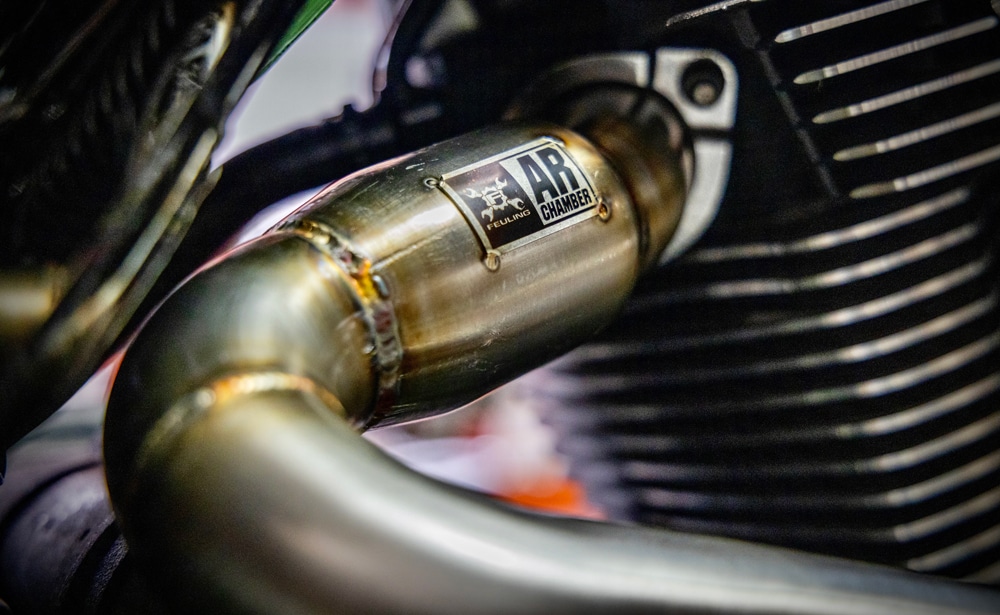
I decided to use a pair of Feuling Parts AR (anti-reversion) Chambers that are designed for a Harley and need to be slightly modified to work on a BSA. They are manufactured in California, legal in 49 states, but not California. They are a passive part, basically just a bulge with an interruption in the exhaust pipe, but in order to get a pair for our use, I ordered them and had them shipped to another state where relatives lived. The California Air Resources Board (CARB) requires testing to be done on aftermarket parts, which costs companies many thousands of dollars for testing before approval, so this part isn’t sold in California. In my wildest dreams, I can see no way this part will affect air quality and they actually might improve it with a cleaner burn. I guess this makes me a fugitive, but I still sleep well at night.
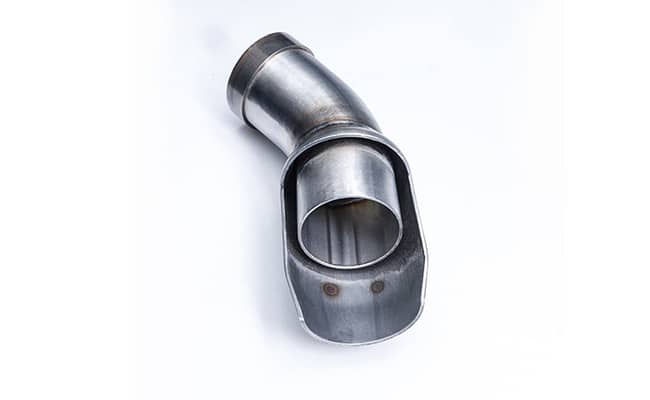
The entrance pipe size for this part is 1-3/4” and the BSA exhaust pipe diameter is 1-1/2”. I think this will work out well for us, as going from a smaller pipe to a larger pipe after a few inches is thought by many to be a good thing. In our case the smaller pipe will exit the head for about 4”, ending up inside the AR chamber. Short pieces of exhaust pipe of different diameters will be used to step up the outside of the BSA pipe to fit and be welded into the AR chamber. The exiting pipe will be a 1-3/4” pipe that will combine into a 2-1/4” merge collector underneath the motor. In theory, all this effort should help performance, but I don’t know this for sure. However, I can’t see any downside in performance, so this is where we are headed. We will cover the exhaust and intake issues in a future post. The exhaust work will probably be one of the last things we do, because everything on the timing side of the bike has to be complete first. We need to know the swing of the kick starter and placement of the foot pegs before we start running exhaust tubing.
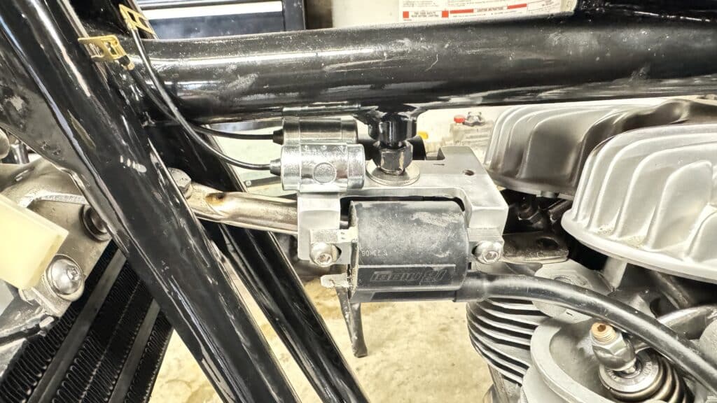
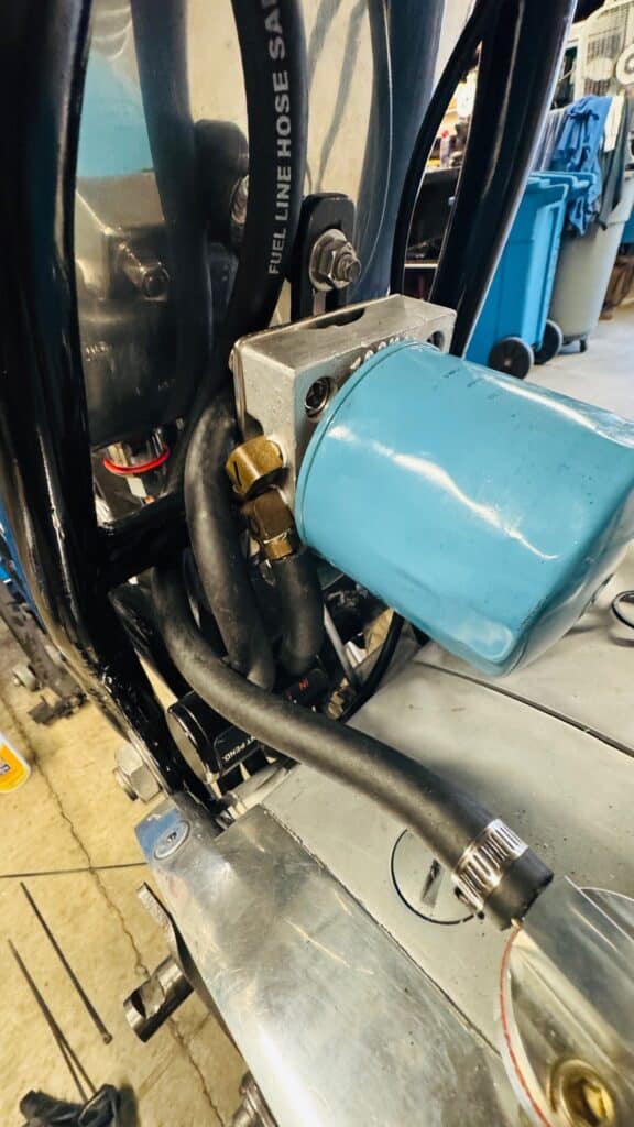
I machined a piece of aluminum to hold the new Nibbi high performance ignition coils under the fuel tank and we ran new oil lines to the oil tank, oil filter, cooler, thermostatic valve and from the engine breather. Running the oil lines on a BSA A-65 is NOT intuitive! In typical British fashion, the oil lines have to crisscross each other coming out of the engine so intuitive running of the lines for feed and return are backwards. Why BSA didn’t correct this with a simple fix is just another of many reasons the British motorcycle industry failed, in my opinion. Failure to crisscross the lines will burn up the motor from no oil reaching the crankshaft or rods. Can’t even imagine how many times this has happened to unaware BSA owners.
Wiring is next. We are using waterproof connectors and we are fairly far along.
This bike is starting to take shape!
I’m sure everyone appreciates your posting of all this specific information about the BSA and I was especially interested in the lathe order and delivery of this what looks like a substantial machine!
Good to see you finally used some Hollywood looking extras for filming and photographing
They don’t come cheap!