1/1/25
Eric is remaking the intake floors to fit our ported head slightly better so we have stopped work on the cylinder head. When the new floors arrive, we will continue with installing new valve guides and seats.
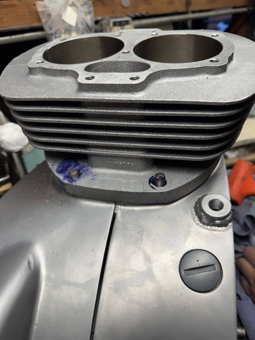
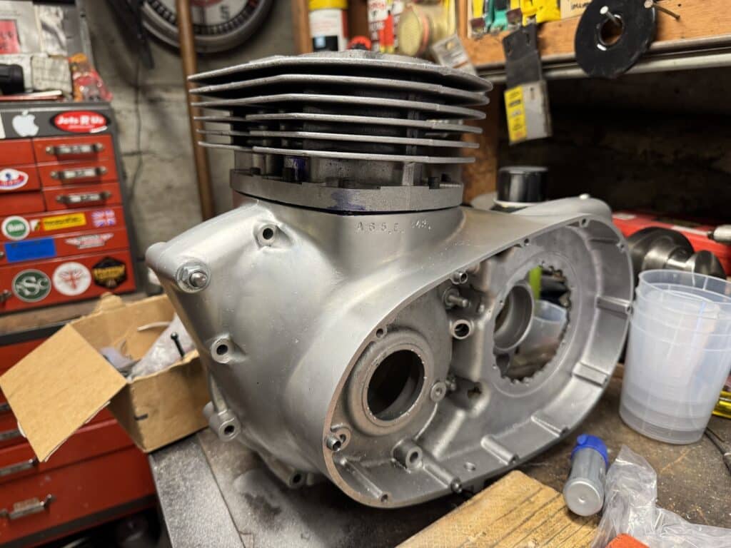
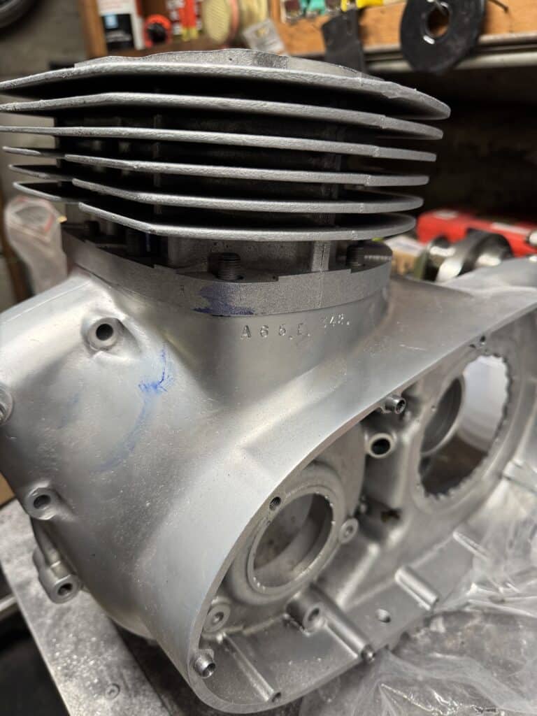
The big news is that after waiting since March, the aluminum cylinder barrels have finally arrived from Ed Valiket (Ed V). They seem well made and the 80mm JE pistons included with them have the proper clearances (.002”) for aluminum barrels. We did spend several hours getting the barrels to fit the cases as they needed to be slightly enlarged for the cylinders to drop into the case. Some of this fitting required more work because we think our early cases are slightly narrower than the later cases. Also, we spent some time enlarging some of the mounting bolt holes as the aluminum casting was slightly off the protruding studs. With blue marking dye, we slowly were able to get everything lined up and seated. They are much lighter than the cast iron barrels and look super. The Nikasil plating has a nice cross hatch honed into it for the rings to seat well.
We decided to build an outrigger ball bearing to support the drive end of the crankshaft. This motor should have almost twice the horsepower as stock, and supporting the crankshaft seems like the prudent thing to do. As the motor is now, the drive sprocket and chain have no outward support other than the drive side (DS) main roller bearing. Mark Parker, a builder/racer of very powerful BSA’s in Australia, machines a plate that holds a ball bearing and attaches to the 3 alternator studs. It sits inside the primary cover and the oil in the primary case lubricates the ball bearing. Mark is using a later case, which is slightly different than ours and I wasn’t crazy about adding sideways load at the far end of 3 not too heavy alternator studs. I felt that this bearing should be held in place at least as rigidly as the DS case bearing in order to keep the crankshaft from flexing under extreme loads. The best option to me was to build a bearing into the outer case cover, which would allow us to straddle the drive sprocket with a bearing on each side.
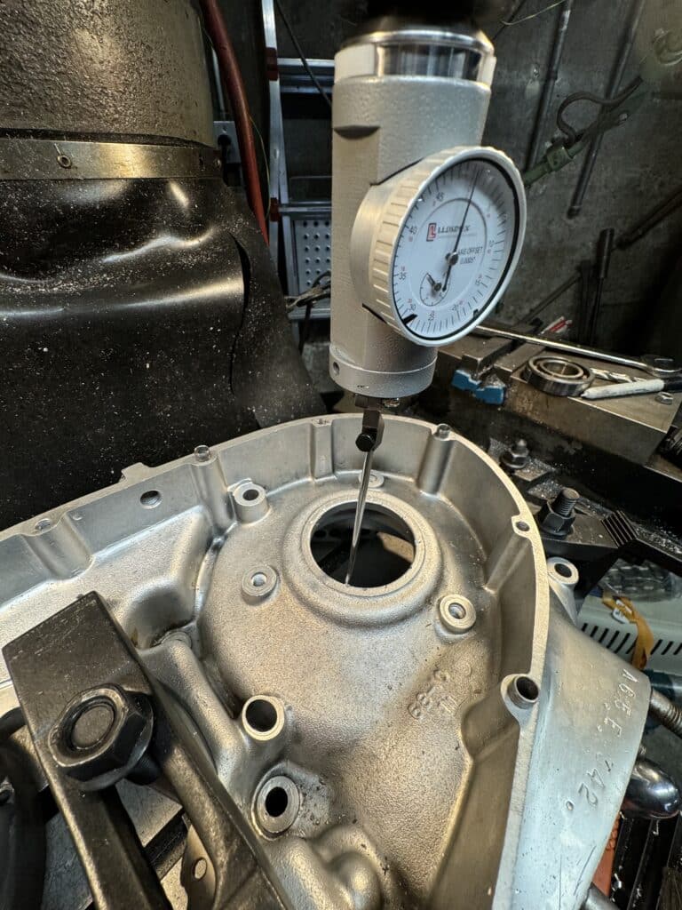
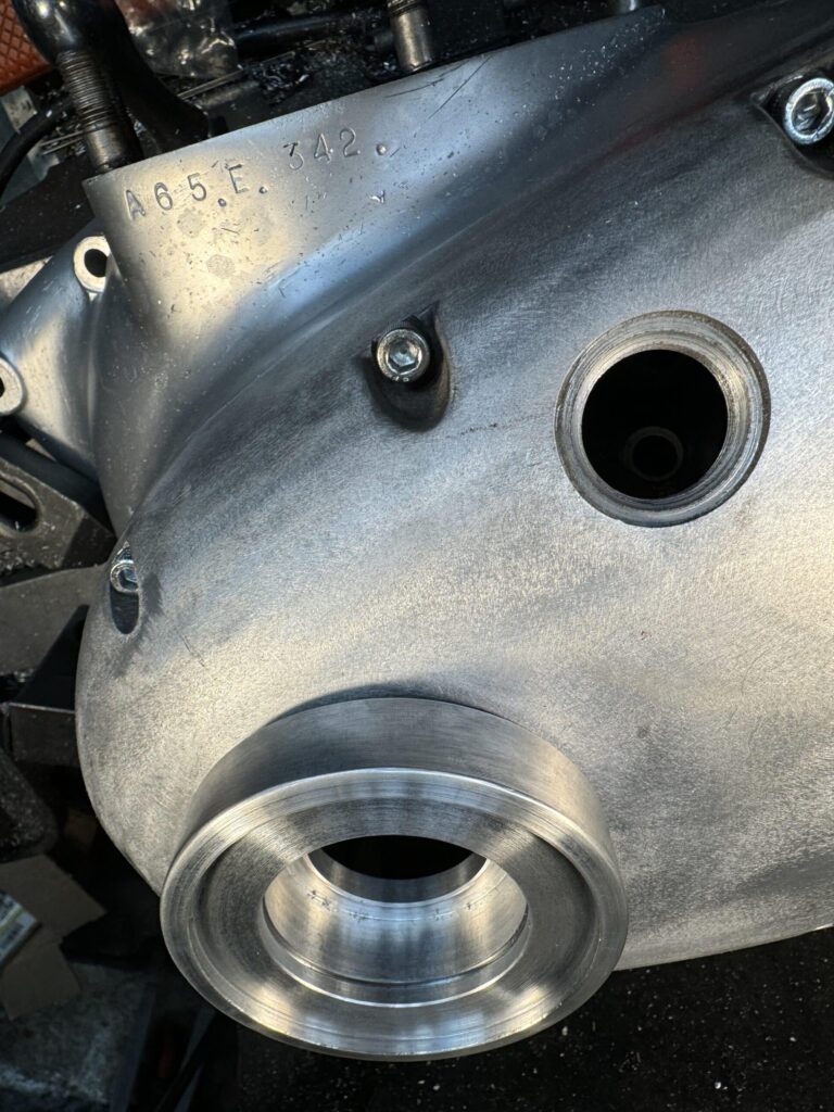
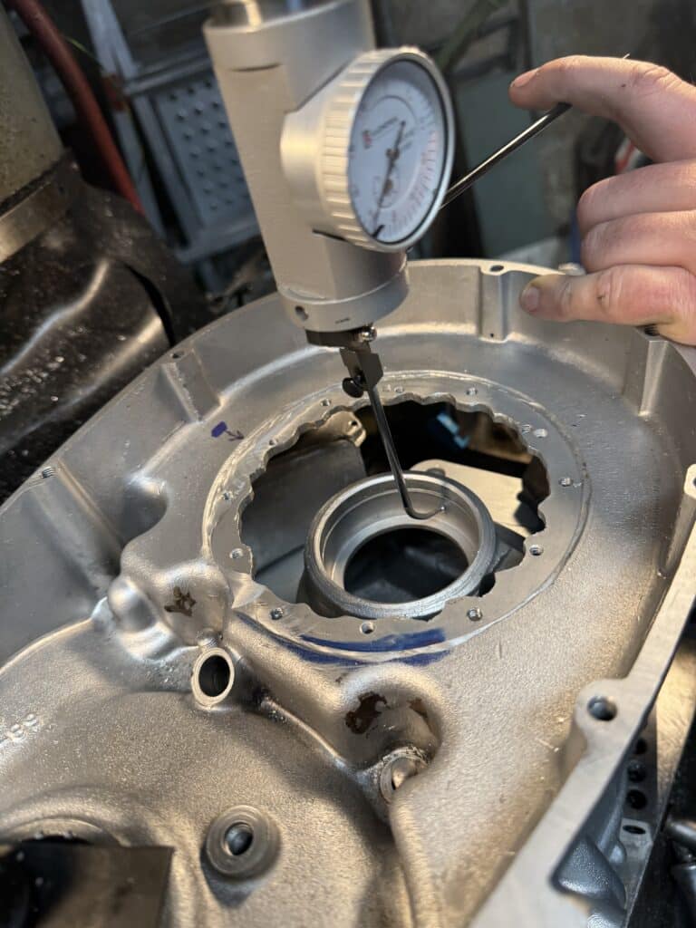
The primary case cover is held in place by about a dozen ¼” bolts. Since we want to use the cover to hold a precision bearing in exactly the centerline of the crank, we first needed to dowel the primary case in 3 places, to insure that it would always be bolted in place exactly in the same position after each removal and replacement. Next we placed the DS case on the mill table, bolted it down and indicated the DS main bearing bore until the needle didn’t move in any direction. Once we were zeroed out on the bearing, we locked the mill in the x and y-axis. We bolted down the newly doweled primary cover and set up a boring head on the mill. BSA has an inspection window that is about 3” in diameter and I wanted to replace this with a bearing holder that I would make on the lathe and weld onto the case.
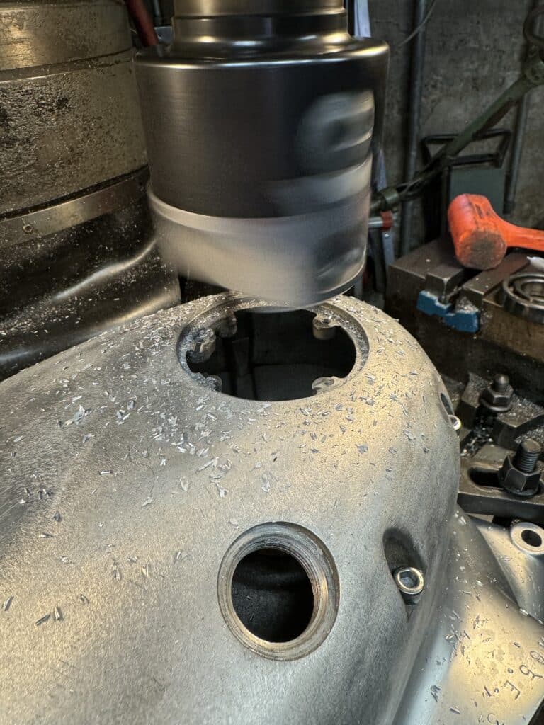
As I expected, the bearing cover recess in the primary case was not quite centered on the crank centerline and also the step in the case for the cover was almost 1/8” out of parallel from the case side. Opening up the hole in the case about 1/16” centered it, and by cutting almost 1/8” down gave me a flat parrell surface to land the bearing holder I would build. We chose an SKF 6205 2RSL-C3 bearing for this holder, held in with a snap ring on the outside of the bearing. It is a double sealed bearing, as it won’t be getting any oil from the primary case. It won’t get oil from the primary case because this case will now be a dry case. We have decided to use a 5-plate dry clutch from Bob Newby Racing with a geared belt drive instead of the triplex chain-drive oil bath stock clutch. There are several advantages to this set-up. It’s lighter, stronger, far less likely to slip under full power, and easier to engage and disengage. Plus, the primary case won’t leak with a dry clutch! I removed the oil seals from the new bearing, cleaned out the grease, and re-packed the bearing with high temperature wheel bearing grease and then replaced the oil seals. A bearing in an oil bath probably would last longer, but this isn’t an option with the new clutch.
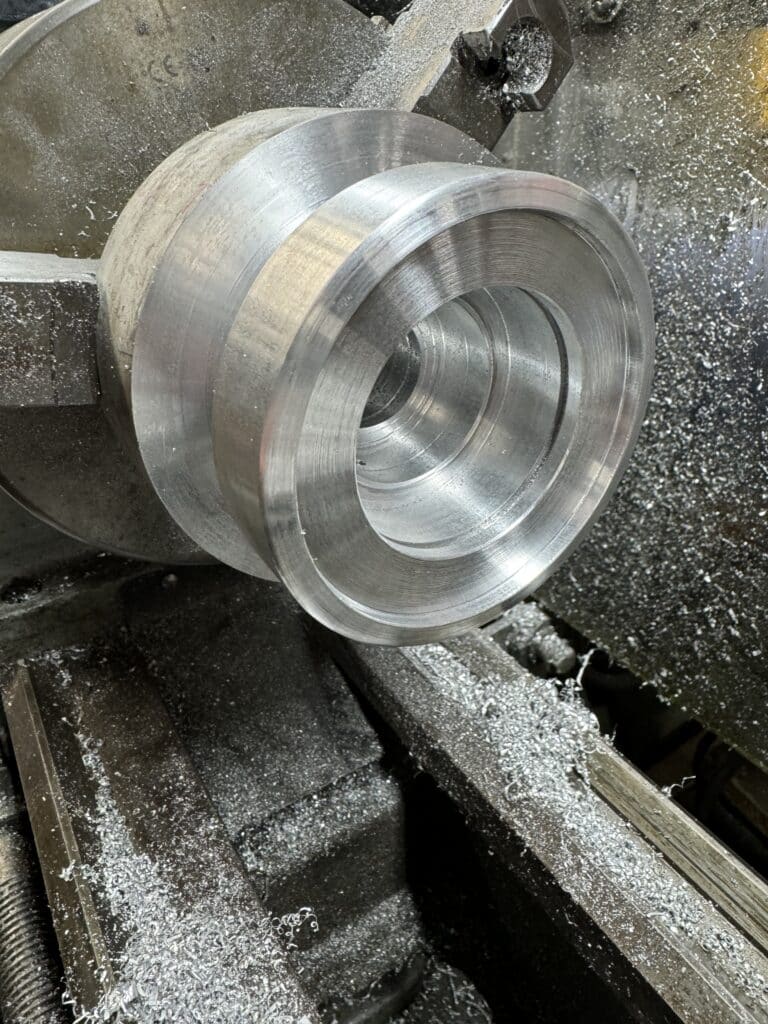
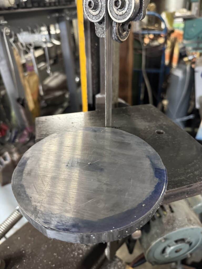
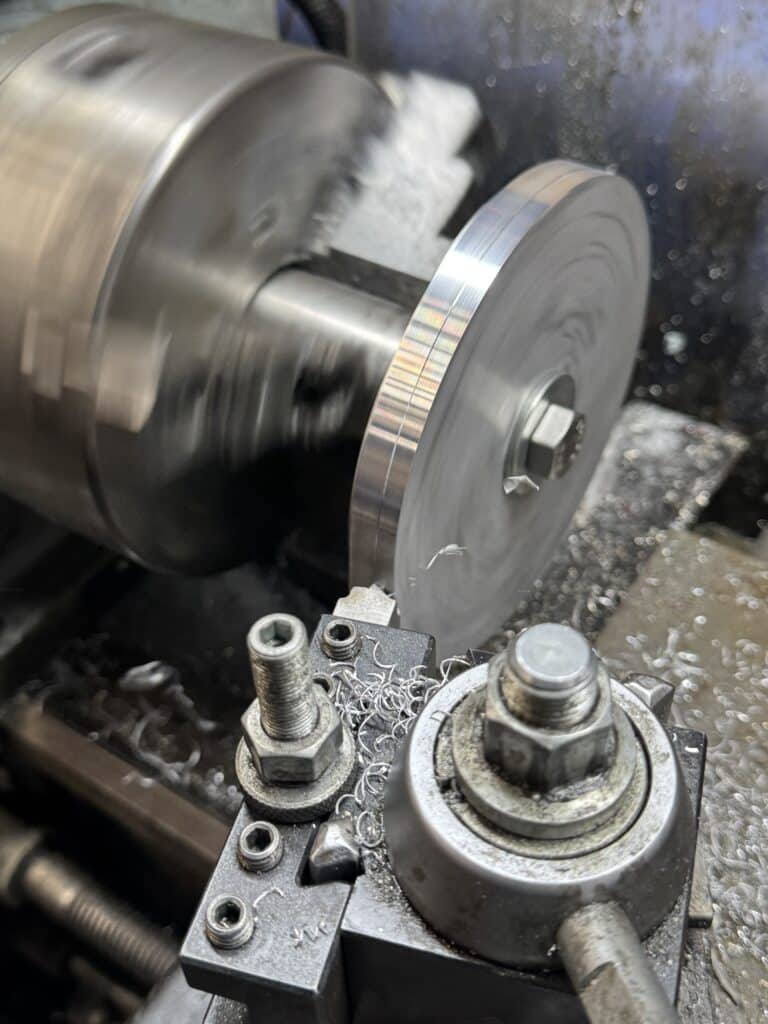
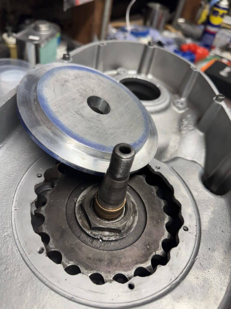
Next I turned a 4” round 6061 block of aluminum into a part that would fit the case we just centered, that would hold the bearing, snap-ring, shaft oil seal and then hold the stock BSA inspection cover. Shawn Campbell welded the bearing holder I made to the primary case. Since I was concerned about warping from the heat of the welding, I left the finished size for the new bearing holder about .050” undersized. Once welded, we bolted on the primary case cover to the DS engine case which was still bolted down and centered on the mill table, and finished bored the cover to size for the new bearing. Now we had all three crankshaft bearings in perfect alignment.
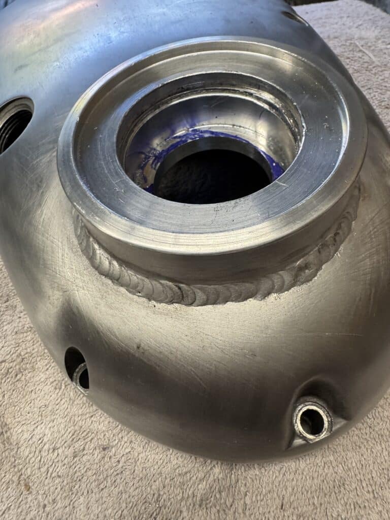
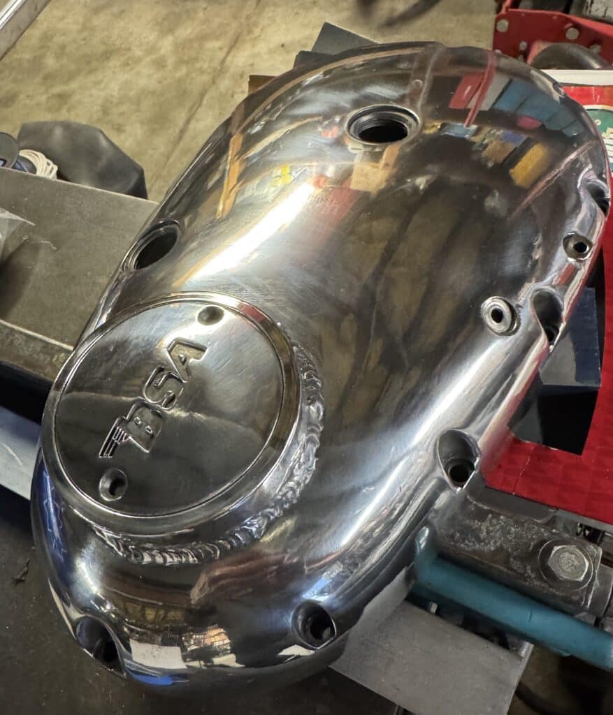
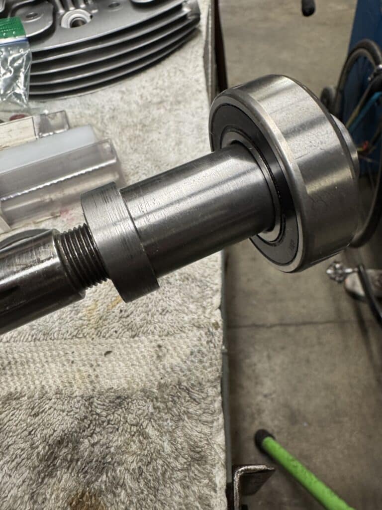
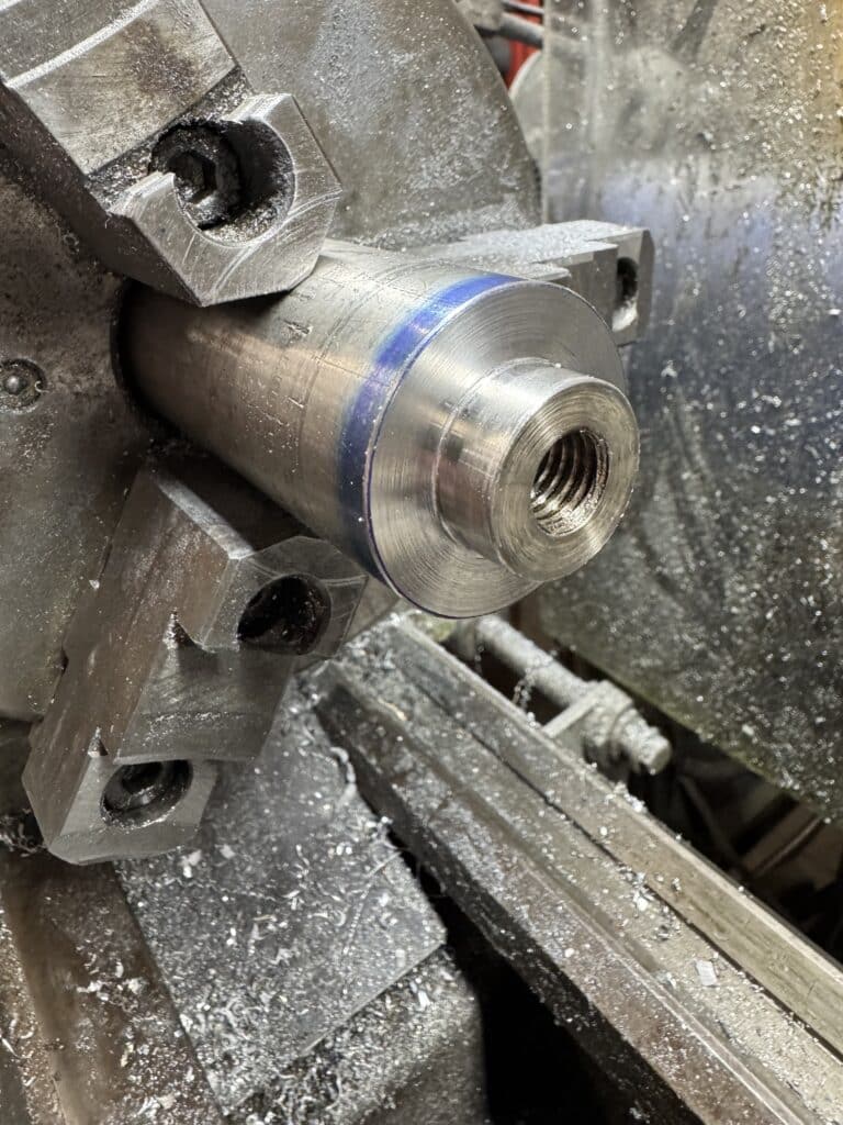
I needed to build an extension shaft for the crankshaft to go into the new outer support bearing. This shaft would be a combination nut to replace the nut that holds the drive sprocket and alternator rotor in place, as well as a 25mm crankshaft extension. The nut end of the shaft has 5/8” internal threads to screw onto the end of the crank and the 25mm shaft will go through the new bearing. When the engine is assembled, I’ll cut off the excess length of the shaft once I know the length. The outside end of the shaft will have internal threads in order for a degree wheel to be screwed onto the shaft for timing the motor. To finish off the new bearing holder, I machined a recess into the end of it to accept the BSA logo cover/inspection plate for a nice finished look.
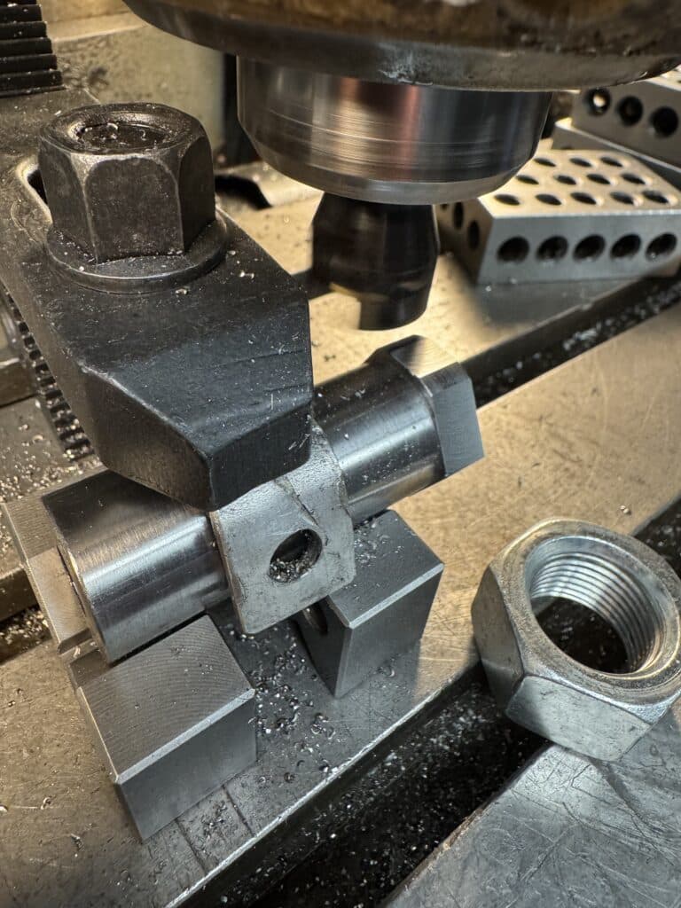
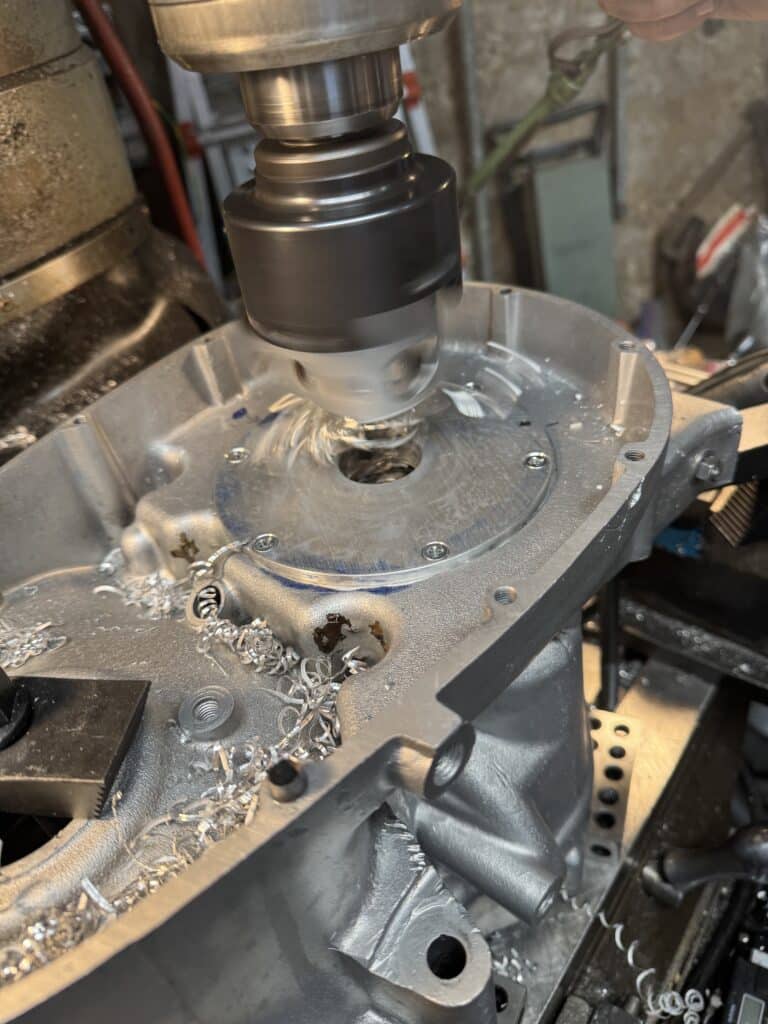
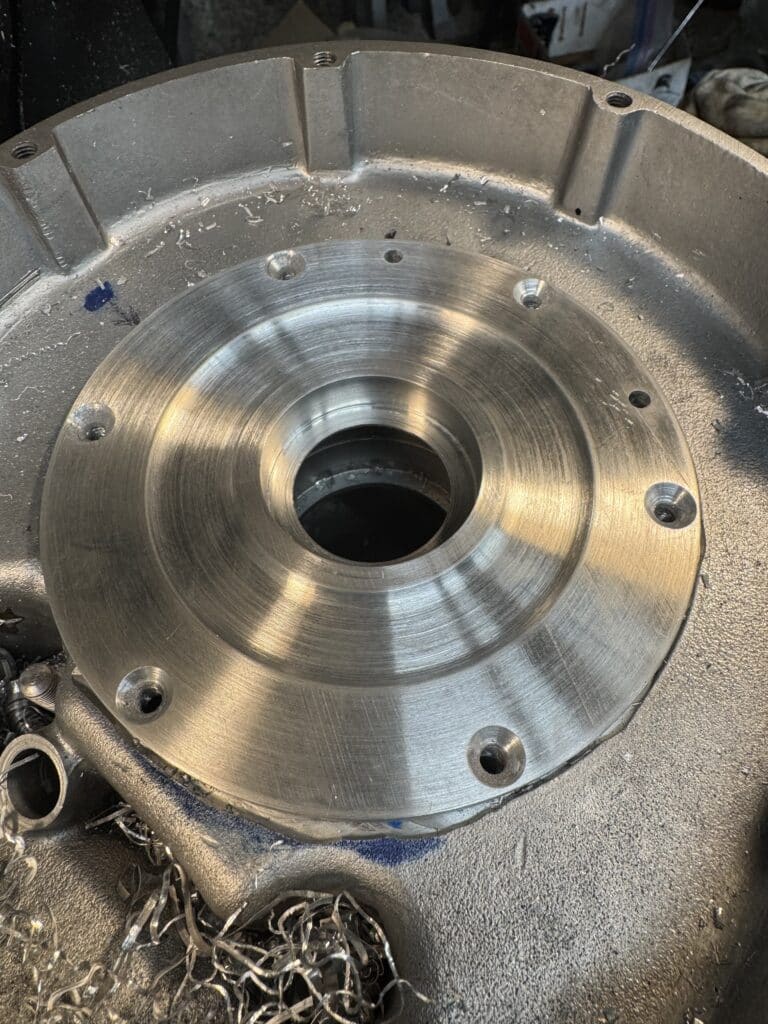
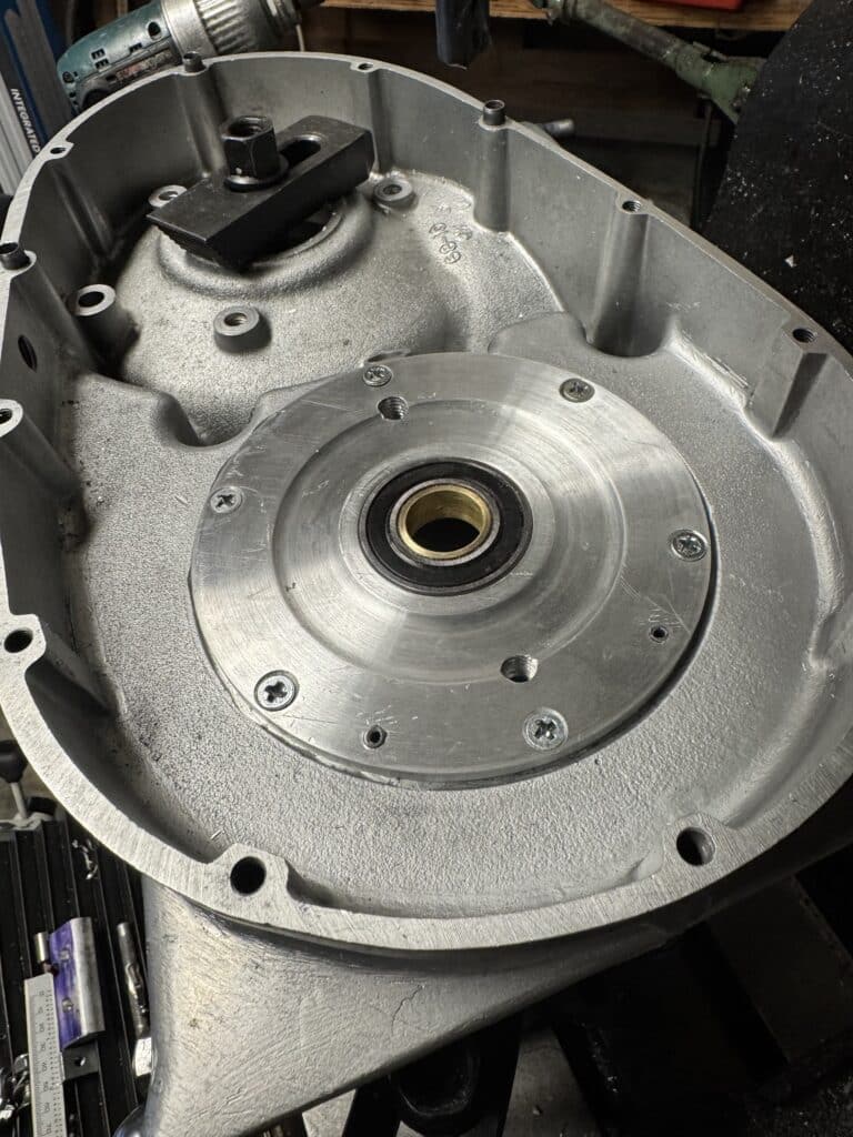
Additionally, I am supporting the final drive (front chain sprocket) transmission main shaft on either side of the sprocket with a ball bearing (SKF 6005-2RSL-C3) in the “trap door” (outrigger plate) cover to the primary case. I wanted to use the slightly larger same bearing we used on the crankshaft, but its 15mm width interferes so we used this one which is 12mm wide. As it is stock, there is an oil seal in this cover where the transmission main shaft goes into the clutch basket.
With a new dry clutch, this oil seal is not needed and a ball bearing can replace it for support on either side of the front sprocket. Performance Engineering Services (PES) casts a plate with a main shaft bearing for a B-50 BSA, but after 3 emails to them to try and determine if it fit an A-65, I gave up and we decided to make our own. They didn’t seem able to answer our questions about their product. The advantage of making our own support is it will be made of plate aluminum, not cast aluminum, which is stronger, but even more important, we can indicate the bore for the new bearing off the transmission main shaft bearing and get perfect alignment with the shaft, as well as dowel pin the cover for repeated alingment. The dowels will give us repeated alignment when it is removed and replaced, something missing with the PES cover, if it even does fit an A65. Our new plate has a slightly larger diameter and we used the digital readout (DRO) on the mill to precisely lay out 6 new countersunk holes on a larger bolt center to hold everything in place. Last, I turned a brass sleeve that resized the inside diameter of the bearing to fit the transmission main shaft and pressed it into the bearing using Loctite bearing retainer. This was then pressed into the new cover with more Loctite. Additionally, I drilled and taped a pair of 3/8-16 threaded holes into the cover, in case the close tolerance bearing fit might require a puller to remove the cover from the main-shaft. I plan to plug these with 3/8″ set screws to keep any road grit from entering the holes as they are right next to the drive chain. The brass bushing on fourth gear was trimmed back to the gear face to allow this modification to work.

The Bob Newby belt drive clutch has arrived and it is a beautiful part, as well as the steel 4340 I-beam Mapp Cycle connecting rods. Next we have to work on the cylinder head and complete it to insure the Megacycle cam we have chosen has the valve clearance we need with the tops of the pistons, our next project.

F’n inspirational
Thanks for the comment. It’s a lot of fun when things go right!!! /Larry